Do you have a question about the Fluidwell F130-P and is the answer not in the manual?
General guidelines, warnings, and precautions for safe operation and installation.
Procedures and guidelines for proper disposal of electronic waste according to WEEE Directive.
Specific rules for installation, operation, and maintenance, emphasizing trained personnel.
Describes the manual's division into user and technician sections, and the use of pictograms.
Provides contact details for warranty and technical support via website or email.
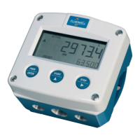
Overview of the batch controller's functions, features, and design focus.
Details on compatible flowmeter signal types, including passive/active pulse, Namur, and coil.
Description of the two passive transistor or relay outputs for control and pulse output.
Details on setup features like K-factors, units, power management, and available options.
Describes the LCD display, backlight, and data backup mechanism.
Basic operating principles, safety for operators, and control panel overview.
Explains the function of each key on the control panel (PROG/ENTER, START, STOP).
Describes how the unit operates in operator mode and how to change batch quantities.
Details on programming preset values, leading zeros, batch limits, starting, and pausing/stopping batches.
Explains clearing batch totals, displaying accumulated totals, low-battery alarms, and no-flow alarms.
Information for electricians/technicians on software settings and hardware connections.
Procedure to access the setup menu, including password requirements.
Explains the menu structure, function groups, and how to navigate using keywords.
Details on using control panel keys for navigation and changing values/items in setup.
Procedures for confirming settings, exiting setup, and returning to normal operation.
Configuration options for unit, decimals, K-factor, batch limits.
Settings related to overrun analysis and time for batch correction.
Configuration for no-flow alarm and associated delay time.
Options for counter behavior and backlight brightness.
Settings for LCD update time and battery mode to optimize power consumption.
Selection of flowmeter signal type, including NPN, Reed, PNP, Namur, and coil inputs.
Configuration for relay outputs, preclose, width, amount, and pulse for batch control.
Configuration for communication speed, address, and mode (Modbus).
Settings for model, software version, serial number, password, and tag number.
Precautions and guidelines for mounting, wiring, and handling the device safely.
Environmental conditions, IP rating, and considerations for cold or humid environments.
Instructions for identifying the device and handling its enclosure, including opening/closing.
Detailed dimensions for aluminum, stainless steel, and non-metallic enclosures.
Various mounting methods including wall, meter, pipe, and panel mounting.
ESD precautions, grounding, compliance with regulations, and cable entry requirements.
General directions for safe electrical practices, including cable selection and wiring standards.
Procedures for grounding metal enclosures, distinguishing common ground from PE.
Guidelines for wiring signals, including screen termination and avoiding ground loops.
Details on external and internal power supplies, including backup functionality.
Configuration of sensor supply voltage for different flowmeter types and power supply options.
Connection details for power supply, including voltage ranges and maximum power.
Configuration for Relay outputs R1 and R2, including active and mechanical relay types.
Details on passive transistor output type OT, including driving capacity.
Connection and setup for various flowmeter inputs: coil, NPN, PNP, active signals.
Specifics for Reed-switch and NAMUR signal inputs, including power supply needs.
How to connect an external switch to start the batch process.
How to connect an external switch to interrupt or cancel the batch process.
Connection details for communication options like RS232, RS485, and TTL.
Information on identifying intrinsically safe models via labels and model codes.
Guidelines for installing the device in hazardous environments, including safety and wiring standards.
Instructions for installation based on ATEX and IECEx directives and product certificates.
Detailed electrical data, maximum values, and conditions for intrinsic safety.
Wiring requirements for power supply types in hazardous areas.
Configuration of sensor supply for intrinsically safe applications.
Overview of terminal connections for intrinsically safe applications, including Type XI.
Details for TTL communication port in intrinsically safe applications.
Example of setting up the F130-P for battery power in IIB/IIC/IIIC areas.
Example of setting up the F130-P with external power in IIB/IIC/IIIC areas.
Routine checks for enclosure, wiring, accuracy, and battery status.
Procedure for returning the product for repair, including RMA process.
Safety precautions and guidelines for handling and replacing batteries, especially in hazardous areas.
Step-by-step guide for replacing old batteries and installing new ones.
Guidelines for the environmentally sound disposal of used batteries.
Details on display type, digits, enclosure materials, and control keys.
Dimensions and classifications for panel and field/wall-mount enclosures.
Specifies operating temperature ranges and relative humidity limits.
Lists available power supply types and sensor supply configurations.
Details on terminal types, data protection, password settings, and hazardous area classifications.
Lists compliance with EMC, Low Voltage, ATEX, IECEx, RoHS, IP, and NEMA standards.
Common issues with flowmeter pulses and their potential causes and checks.
Issues related to pulse output not functioning and what to do if the password is unknown.
Explains how to interpret alarm codes and when to contact support.
Describes Modbus protocol support, function codes, and PDU addresses.
Details on runtime variables like total, preset, and error status accessible via Modbus.
Lists setup variables for Preset, Overrun, Display, Power Management, etc., with PDU addresses.
Details Modbus speed, address, mode, and other settings like model, firmware, serial number.
Communication variables for batch mode, keylock, command execution, and preset quantity.
States compliance with European Directives and Harmonised Standards for F1-Series indicators.
States compliance with UK Legislation and Standards for F1-Series indicators.
| Category | Controller |
|---|---|
| Display Type | LCD |
| Protection Rating | IP65 |
| Input Type | Analog, Digital |
| Output Type | Relay, Analog |
| Power Supply | 24 VDC |
| Operating Temperature | -20°C to +60°C |