Theory of Operation
VCHEK Input Resistance
2
2-5
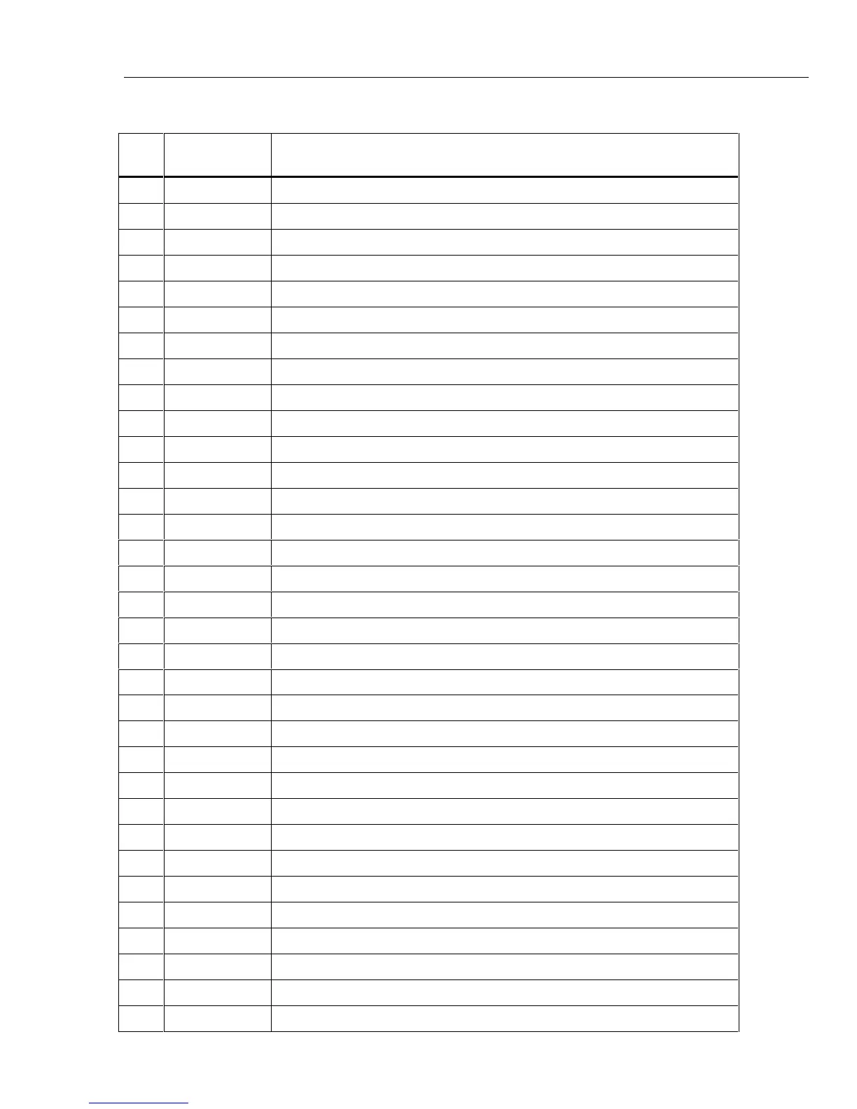
Table 2-2. U1 Pinout Table
Pin
No.
Pin Name Description
1 READ(L) When low (VSS), data from addressed register can be read.
2 ADR5 Most significant address bus line.
3 ADR4 Bit 4 of parallel address bus.
4 ADR3 Bit 3 of parallel address bus.
5 ADR2 Bit 2 of parallel address bus.
6 ADR1 Bit 1 of parallel address bus.
7 ADR0 Least significant address bus line.
8 VSS Negative power supply voltage (-3V relative to DGND).
9 VDD Positive power supply voltage for analog only (Vbat-3V=VDD-DGND).
10 K0 1st a/d gain resistor pin, generally for de-integrate.
11 K1 2nd
a/d gain resistor pin, generally for intergrate.
12 K2 3rd a/d gain resistor pin, for autozero.
13 AZ A/D converter pin for autozero capacitor.
14 INT A/D converter pin for integrator capacitor.
15 REFI 1.00V reference voltage for de-integrate signal in volts.
16 BIAS Pin for analog bias current generator reference resistor.
17 REFH Connects 1.235V reference voltage to on-chip circuits.
18 BGND Not used.
19 AFO Active filter high output pin (2-pole, low-pass filter).
20 FAO Internal active filter node.
21 FAI Internal active filter node.
22 AFI Active filter high input pin.
23 VSS Negative power supply voltage (-3V reletive to DGND).
24 PFO Passive filter low output pin (1-pole, low-pass filter).
25 AVAOM Absolute value amp (full wave rectified) negative output pin.
26 AVAOP Absolute value amp (full wave rectified) positive output pin.
27 AVAM Absolute value amp inverting input (summing node).
28 ACBO AC buffer output.
29 VSET Voltage divider sense for power supply.
30 PSTEST Pin to disable on-chip power supply for U1 testing.
31 DGND Ground power supply pin connected to common (digital ground).
32 AGND Common input sense line. No current flow (Analog ground).
33 CLAMP Op amp output voltage for Q2 clamp transister base drive.