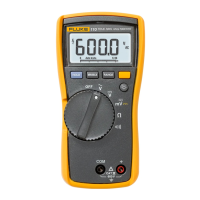
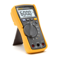
114, 115, 116, and 117
Calibration Information
16
Table 4. Calibration Adjustment Steps (cont)
Calibration Steps
Rotary
Switch
Position
114 115
[1]
116
[1]
117
[1,2]
Input
Terminals
Calibrator
Source Value
$
DC μamps
N/A N/A C23 N/A + and COM 600 μA, 0 Hz
[1] Models listed in this column also refer to the “C” version of the model. For example, model 115 steps are valid for the 115C.
[2] Do not calibrate the 117 or 117C with a line-frequency power source nearby (e.g. fluorescent light, power strip, etc.). These devices
can produce errors in the VoltAlert calibration.
[3] Wait an additional 5 seconds after calibrator has settled before pressing g.

 Loading...