15B & 17B
Calibration Manual
8
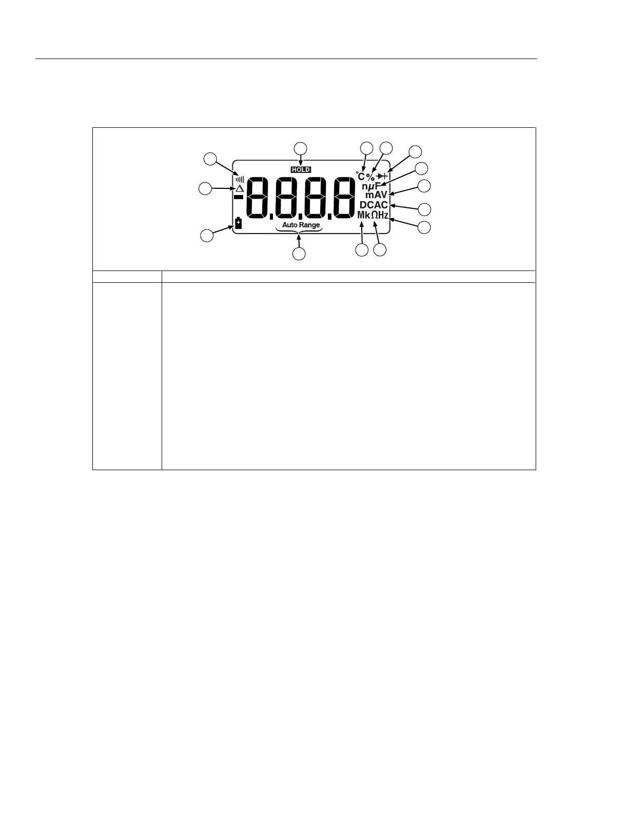
Testing the Display
Turn the UUT on and off several times and observe the display. Make sure that all of the
display segments and icons show up as in the Figure 1.
2
7
6
8
9
10
14
1
3
4
5
11
12
13
apg2f.eps
Icon Number Description
A
Relative mode is active
B Continuity selected
C
Display Hold is enabled
D Temperature is selected
E Duty Cycle is selected
F
Diode test is selected
G F – Farads for capacitance
H A, V – amps or volts
I
DC, AC – dc or ac voltage or current
J Hz - Frequency is selected
K O - Ohms is selected
L
m, M, k – decimal prefix
M Auto range selected
N Battery is low and should be changed
Figure 1. Display
Performance Test Procedures
To test each of the Meter’s functions and operating ranges, do the following:
1. Referring to the performance test tables (Tables 3 and 4), set the Meter to the desired
function and range for each test.
2. Connect the source to the appropriate UUT’s input jacks.
3. Apply the indicated output from the source.
4. The reading on the UUT display should be within the low and high limits shown in
Table 3 or 4.
5. Repeat steps 1-4 for each function and range in the performance test tables.
If the UUT fails to perform within the low-high range indicated for each test in Table 3 or
Table 4, adjust the Meter and go through the performance test procedure again. If the
UUT still fails to perform within the ranges indicated, then repair is necessary. Refer to
“Contacting Fluke” to locate a service center.
 Loading...