15B & 17B
Users Manual
8
AC
apg4f.eps
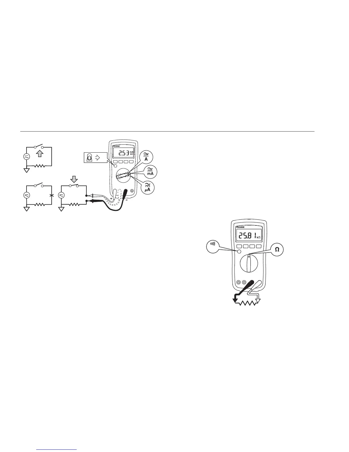
Figure 2. Measuring AC and DC Current
Measuring Resistance
XW Warning
To prevent possible electrical shock, fire, or
personal injury, disconnect power and
discharge all high-voltage capacitors before
you measure resistance, continuity,
capacitance, or a diode junction.
1. Turn the rotary switch to
. Make sure power is
disconnected from the circuit to be measured.
2. Connect the red test lead to the
terminal and the
black test lead to the COM terminal.
3. Measure the resistance by touching the probes to the
desired test points of the circuit.
4. Read the measured resistance on the display.
Testing for Continuity
With the resistance mode selected, press the YELLOW
button twice to activate the continuity beeper. If the
resistance is under 50 Ω, the beeper will sound
continuously, designating a short circuit. If the meter reads
, the circuit is open.
<50
apg5f.eps
Figure 3. Measuring Resistance/Continuity