Do you have a question about the Fluke 189II/AN and is the answer not in the manual?
Information on how to contact Fluke for support or orders.
Explanation of symbols used in the manual and on the meter.
Guidelines to prevent electric shock, injury, or damage to the meter.
Specifies AC voltage measurement ranges, resolution, and accuracy across frequencies.
Details AC current measurement ranges, resolution, and accuracy across frequencies.
Outlines DC voltage measurement ranges, resolution, and accuracy.
Details DC current measurement ranges, resolution, and accuracy.
Specifies resistance measurement ranges, resolution, and accuracy.
Provides temperature measurement ranges, resolution, and accuracy.
Details specifications for capacitance and diode testing functions.
Specifies frequency counter ranges, resolution, and accuracy.
Details specifications for MIN/MAX, recording, and peak measurement functions.
Describes overload protection, input impedance, and rejection ratios.
Specifies burden voltage for current measurement ranges.
Procedure for inspecting meter contents for shipping damage.
Explains how analog signals are processed for measurement.
Describes the µP and memory responsible for user interface and control.
Details the meter's internal power generation from battery voltage.
Visual representation of the meter's internal functional blocks.
Guidance on troubleshooting and identifying faults.
Refers to the "Performance Tests" section for restoration actions.
Step-by-step instructions for safely opening the meter's case.
Procedure for removing and reinstalling the main circuit board.
Steps for correctly reassembling the meter case after service.
Method for testing the internal fuses of the meter.
Instructions for safely replacing the meter's fuses with correct types.
Procedure for replacing the meter's batteries, noting polarity.
Guidelines for cleaning the meter case and input terminals.
Steps to reset the meter to its factory default settings.
How to verify the functionality of the meter's power button LED.
Procedure to test the meter's display backlight.
Verifies the functionality of the Input Alert™ feature.
Method to ensure all keypad buttons are active and responsive.
Procedure to check the integrity and functionality of the LCD display pixels.
Steps to verify communication through the meter's IR port.
Procedure to test the accuracy of the temperature measurement function.
Comprehensive tests for verifying accuracy across various measurement functions.
Overview of initiating and navigating the calibration process.
Steps to enter the required password for calibration.
Procedure to modify the existing calibration password.
How to reset the calibration password to the default value.
Detailed steps and guidance for performing meter calibration.
Explanation of the elements shown in the calibration adjustment screenshot.
Describes the function of softkeys during calibration.
Explains how navigation buttons function during calibration.
Notes which mode buttons are disabled during calibration.
General guide on performing calibration steps and interpreting results.
Specific sequence and parameters for calibrating the meter.
| Resistance Measurement | Yes |
|---|---|
| Frequency Measurement | Yes |
| Safety Rating | CAT III 1000 V, CAT IV 600 V |
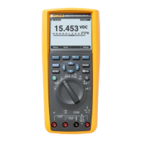
| Display Type | LCD |
| Max Voltage Measurement | 1000 V |
| Basic DC Voltage Accuracy | 0.025% |
| Max Current Measurement | 10 A |
| Data Logging | Yes |
| Battery Type | 2 x AA |