True-rms Digital Multimeter
Unpacking the Meter
9
Input Characteristics
Function
Overload
Protection
[1]
Input
Impedance
Common Mode
Rejection Ratio
(1 kΩ unbalance)
Normal Mode Rejection
L
1000 V
10 MΩ <100 pF
>120 dB at dc,
50 Hz or 60 Hz
>60 dB at 50 Hz or 60 Hz
F
mV
1000 V
[2]
10 MΩ <100 pF
>120 dB at dc,
50 Hz or 60 Hz
>60 dB at 50 Hz or 60 Hz
K
1000 V
10 MΩ <100 pF
(ac-coupled)
>60 dB, dc to 60 Hz
Full Scale Voltage Typical Short Circuit Current
Function
Overload
Protection
[1]
Open Circuit
Test Voltage
To
500 kΩ
≥5 MΩ or
50 nS
500 Ω 5 kΩ 50 kΩ 500 kΩ 5 MΩ 50 MΩ 500 MΩ
e
1000 V
[2]
5 V dc 550 mV <5 V 1 mA
100 μA 10 μA
1 μA 1 μA 0.3 μA 0.3 μA
G
1000 V
[2]
5 V dc 3.1 V dc 1 mA
[1] Input is limited to the product of a V rms sinewave times frequency of 2 x 10
7
V-Hz.
[2] For circuits <0.5 A short circuit. 660V for high energy circuits.
Burden Voltage (A, mA,
μ
A)
Function Range Burden Voltage
500 μA 102 μV/ μA
5000 μA 102 μV/ μA
50.000 mA 1.8 mV/mA
mA, μA
400.00 mA 1.8 mV/mA
5.0000 A 0.04 V/A A
10.000 A 0.04 V/A
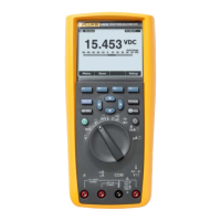
Unpacking the Meter
Open the Multimeter box. Inside will be found a 189II/AN Digital Multimeter, one set of
test leads, a Product Manuals CD, a 189II/AN Users Manual, and a 189II/AN Service
Manual. Remove the Meter from its plastic wrapping.
Inspection
Inspect all contents for any visible shipping damage. Look for scratches or any other
damage. If the Meter is damaged, contact Fluke immediately using the contact
information listed in the “Contacting Fluke” section earlier in this manual. If it is
necessary to return the Meter, place it in its original packaging and return.
 Loading...


