Series III Multimeter
Performance Tests
13
WWarning
To avoid electric shock, connect the ground/common/low side of the dc
calibrator to common on the UUT.
Testing the DC Voltage Function
1. Set the UUT to L (V dc) and connect the dc voltage calibrator output to the VΩG and COM input
terminals of the UUT.
2. Referring to Table 3, set the dc voltage calibrator for the output indicated in the steps. Verify that the
UUT display reading is within the limits shown.
3. Reset the source to 0 V.
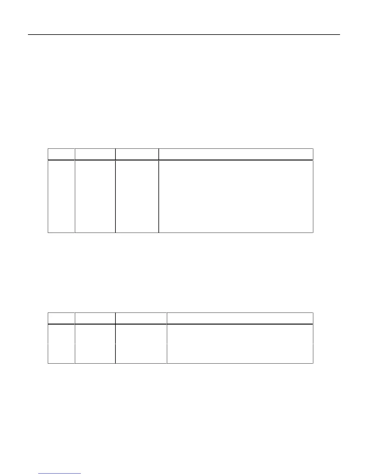
Table 3. DC Voltage Test
Step Range Voltage Display Reading
1 4 V short 0 to ± .001 V dc
2 4 V +3.5 V 3.488 to 3.512 V dc
3 4 V -3.5 V -3.488 to -3.512 V dc
(and within 2 counts
of +3.5 V reading)
4 40 V +35 V 34.88 to 35.12 V dc
5 400 V +350 V 348.8 to 351.2 V dc
6 1000 V +1000 V 996 to 1004 V dc
Testing the mV DC Function
1. Set the UUT to
m
L (mV dc), and connect the dc voltage calibrator output to the VΩG and COM input
terminals of the UUT.
2. Referring to Table 4, set the dc voltage calibrator to the voltage indicated in the steps. Verify that the
UUT display reading is within the limits shown.
3. Reset the source to 0 V.
Table 4. mV DC Voltage Test
Step Range Voltage Display Reading
1 400 mV +350 mV 348.8 to 351.2 mV dc
2 40 mV short 0 to ± .05 mV dc
3 40 mV +35 mV 34.84 to 35.16 mV dc
4 40 mV -35 mV -34.84 to -35.16 mV dc