Series III Multimeter
Basic Maintenance
9
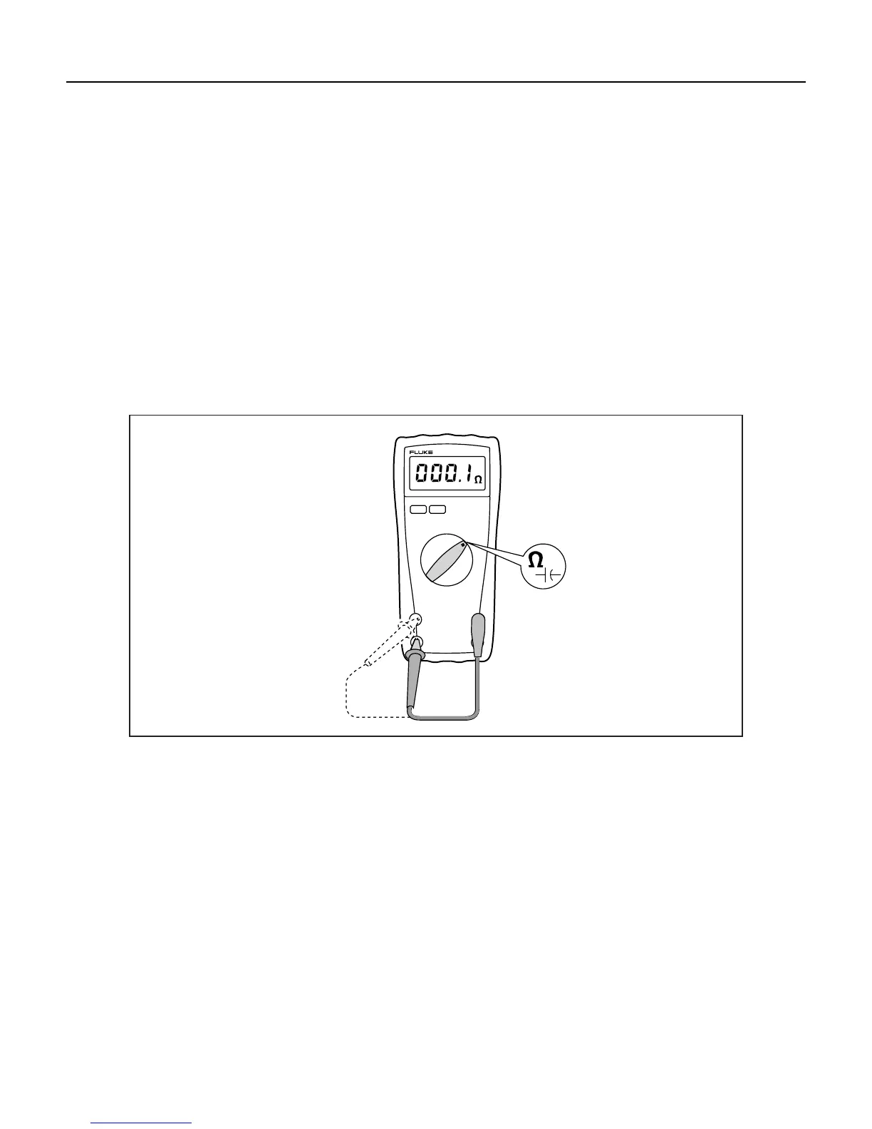
Testing Fuses
Refer to Figure 3, and use the following procedure to test the internal fuses of the Meter:
1. Turn the rotary switch to the Ω E position.
2. To test the F2 fuse (11 A, 1000 V), plug a test lead into the VΩG input terminal and touch the probe
to the 10 A input terminal.
3. The display should read between 0.1 Ω and 0.5 Ω.
If the display reads OL (overload), replace the fuse and test again. If the display reads any other value,
further servicing is required.
4. To test the F1 fuse (F44/100, 1000 V), move the probe from the 10 A input terminal to the 40 mA input
terminal.
5. The display should read between 10 Ω and 12 Ω.
If the display reads a high resistance or OL (overload), replace the fuse and test again. If the display
reads any other value, further servicing is required.
RANGE
pd001f.ep0s
Figure 3. Fuse Testing
Replacing Fuses
W Warning
To avoid possible arc blasts and injuries that result from the blasts, install only
specified replacement fuses with the speed, amp interrupt rating, and voltage
ratings that are shown in Table 12.
Refer to Figure 2, and use the following procedure to examine or replace the Meter’s fuses:
1. Remove the top case as described under “Opening the Meter Case.”
2. Remove the defective fuse by gently prying one end of the fuse loose and sliding the fuse out of the
fuse bracket.
3. Install only the specified replacement fuses with the speed, amp interrupt rating, and voltage ratings
that are shown in Table 12.