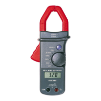
The Fluke 301D/301E Clamp Meter is a versatile handheld device designed for electrical measurements, including current, voltage, resistance, continuity, diode testing, capacitance, and frequency. The 301D/301E models are capable of measuring both AC and DC current.
Function Description
The core function of the Clamp Meter is to provide accurate electrical measurements across various parameters. It features a jaw for non-contact current measurement, test lead inputs for voltage, resistance, continuity, capacitance, and diode tests, and a control knob for selecting different measurement functions.
Basic Measurements:
- AC Voltage Measurement with Test Leads: To measure AC voltage, the user rotates the control knob to the V~ function, connects the black test lead to the COM terminal and the red test lead to the VΩ terminal, and then touches the probes to the test points of the circuit. The display will show the AC voltage.
- Hz under AC Voltage Measurement with Test Leads: For frequency measurement under AC voltage, after setting the knob to V~, the user presses the yellow button to shift to the Hz function. Test leads are connected as for AC voltage, and probes are touched to the circuit.
- DC Voltage Measurement with Test Leads: Similar to AC voltage, the control knob is set to V=, test leads are connected to COM and VΩ, and probes are applied to the circuit to display DC voltage.
- Resistance/Continuity: To measure resistance or continuity, the control knob is set to the Ω/continuity/diode function. Power must be removed from the circuit first. Test leads are connected to COM and VΩ, and probes are touched to the circuit. If resistance is less than 30 Ω, a beeper sounds for continuity. An "OL" display indicates an open circuit or a value higher than the measurement range.
- Capacitance: The Clamp Meter measures capacitance by charging a capacitor with a known current and then calculating the capacitance from the resulting voltage. The control knob is set to the Ω/continuity/diode function, and the yellow button is pressed to shift to the capacitance function. It is crucial to remove the capacitor from the circuit and discharge it safely before connecting the test leads (COM and VΩ) to the capacitor leads. An "OL" display indicates a faulty capacitor or a value exceeding the measurement range.
- Test Diodes: For diode testing, the rotary switch is set to the Ω/continuity/diode function, and the yellow button is pressed twice to shift to the diode function. The red test lead connects to VΩ and the black to COM. The red probe is connected to the anode and the black to the cathode of the diode. The display shows the forward bias voltage. Reversing the polarity of the test leads will show "OL", which helps distinguish anode and cathode.
- Amps AC Measurement with Jaw: To measure AC current, the control knob is set to the A~ function, and the clamp jaw is positioned around the conductor. The display shows the AC current.
- Hz under Amps AC Measurement with Jaw: For frequency measurement under AC current, after setting the knob to A~, the user presses the yellow button to shift to the Hz function, and then positions the clamp jaw around the conductor.
- Amps DC Measurement with Jaw: To measure DC current, the control knob is set to the A= function. Before clamping any conductor, the user presses the yellow button to compensate (zero) the meter. Once "Zero" disappears, the clamp jaw is positioned around the conductor, and the display shows the DC current.
Usage Features
The Fluke 301D/301E Clamp Meter incorporates several features to enhance usability and safety:
- Hazardous Voltage Indicator: The Product includes a hazardous voltage indicator (f) that appears on the display when it senses a voltage greater than ±30V or a voltage overload (OL) at voltage functions, even if the HOLD function is active. This alerts the user to potentially dangerous conditions.
- Tactile Barrier: The device is designed with a tactile barrier, emphasizing the importance of holding the Product behind this barrier to prevent possible electrical shock, fire, or personal injury.
- Power Management:
- Auto Power Off: To conserve battery life, the Clamp Meter automatically powers off after 20 minutes of inactivity. The auto power off feature is indicated by a symbol on the display. It can be disabled via power-on options.
- Backlight: The display features a backlight for improved readability in dim environments. It can be toggled on/off by pressing the yellow button for more than 2 seconds. The backlight also has an auto-off feature after 2 minutes of inactivity, which can be disabled.
- Power-On Options: These options allow for customization of the Clamp Meter's behavior:
- Disable Auto Power Off: Hold down the HOLD button while turning the Clamp ON. The display will show "POFF".
- Disable Auto Backlight Off: Hold down the yellow button while turning the Clamp ON. The display will show "LOFF".
- View Firmware Version and Light All LCD Segments: Hold down either the HOLD button or the yellow button while turning the Clamp ON to view the firmware version and illuminate all LCD segments for a display test.
- Display Hold: The HOLD function allows the user to capture and freeze the current reading on the display. When HOLD is active, "HOLD" is continuously shown. If a hazardous voltage (more than ±30 V or OL) is detected while in HOLD mode, the hazardous voltage indicator (f) will appear. Pressing HOLD again resumes live readings.
Maintenance Features
The Fluke 301D/301E Clamp Meter is designed for minimal routine maintenance, primarily focusing on cleaning and battery replacement.
- Cleaning the Case: The case should be wiped with a damp cloth and mild detergent. It is important to avoid using abrasives, isopropyl alcohol, or solvents, as these can damage the case or lens/window. Before cleaning, all input signals must be removed from the Product.
- Battery Replacement: The Clamp Meter is powered by two AAA batteries. Users are advised to replace batteries when the low battery indicator appears to ensure accurate measurements. The battery door must be closed and locked before operation. All probes, test leads, and accessories should be removed before opening the battery door. If the calibration seal in the battery compartment is damaged during battery changes, the Product should be returned to Fluke for seal replacement, as it may no longer be safe to use.
- Battery Leakage Prevention: To prevent damage or shock hazards from battery leakage, users should repair the Product if battery leakage occurs. Batteries should not be exposed to heat sources or high-temperature environments. If the Product is not used for an extended period or stored in temperatures above 50 °C, the batteries should be removed.
- Service and Calibration: The Product does not require routine maintenance by the user. However, Fluke recommends having an authorized Fluke Calibration service center service the Product at one-year intervals to maintain optimum performance. Contact information for service or maintenance scheduling is available through Fluke's website or customer service. Only specified replacement parts should be used, and repairs should be performed by an approved technician.
- Environmental Disposal: The Product contains electronic printed circuit boards and should be disposed of professionally and environmentally appropriately. Any personal data on the Product should be deleted before disposal. Batteries that are not integrated into the electrical system should be removed and disposed of separately. If the Product has an integral battery, the entire Product should be disposed of as electrical waste.