ClampMeters
Performance Tests
7
Performance Test Procedure
To test each of the Meter’s functions and operating ranges, do the following:
1. Connect the source to the Meter’s VΩ and COM input jacks.
2. Referring to Table 2 for the 321 and Table 3 for the 322, put the Meter in the desired function and
range for each test.
3. Apply the indicated output from the 5520A Calibrator.
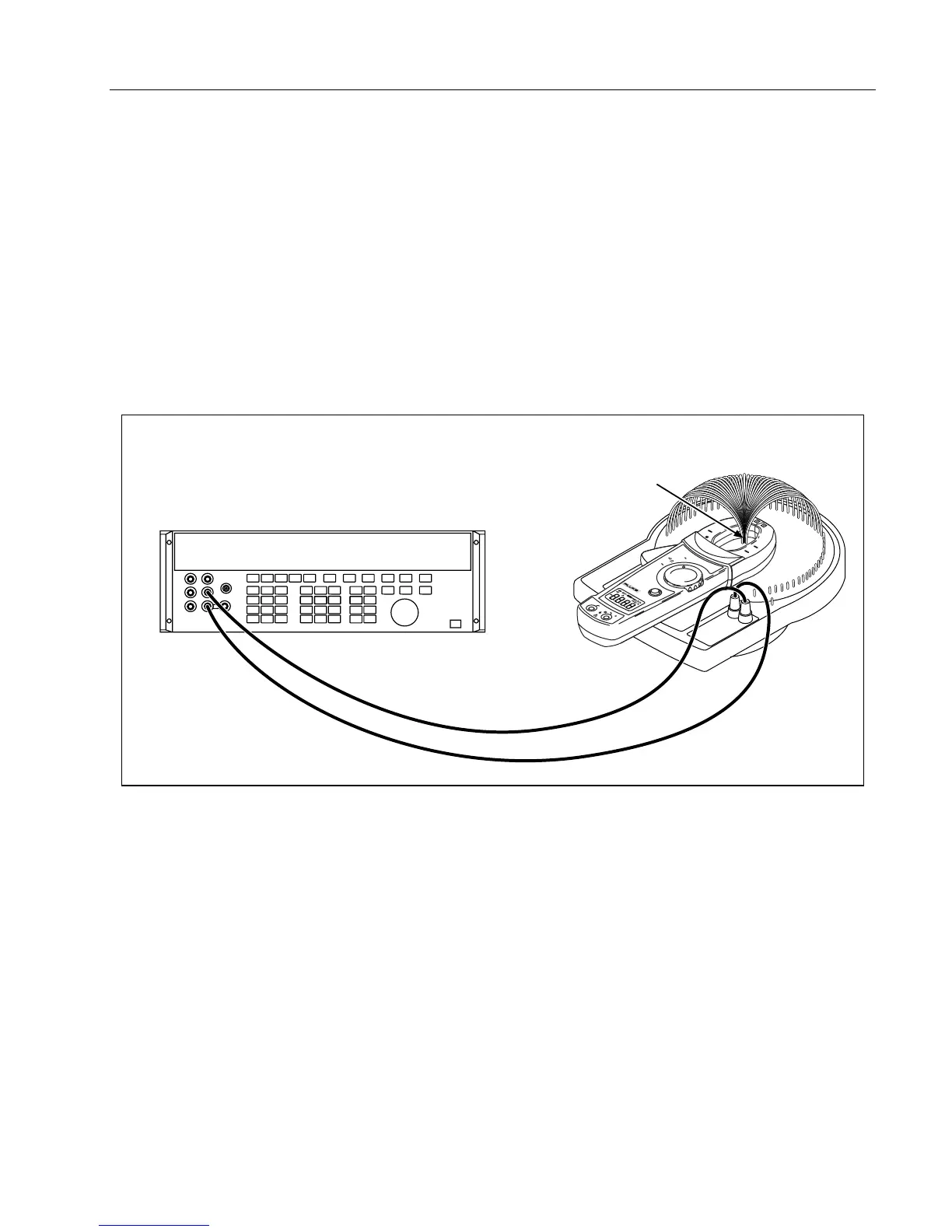
4. When using the amp function on the 5520A, make sure LCOMP on the 5520A is ON.
5. The reading on the Meter display should be within the low and high limits shown in the table.
6. Repeat steps 1-4 for each function and range in Table 2 or Table 3.
If the Meter fails to perform within the low-high range indicated for each test in Table 2 or Table 3, the
Meter needs to be calibrated and adjusted, or requires some repair.
5520A Calibrator
50-Turn Current Coil
Conductor
400A
600V
CAT
CLAMP METER
OFF
HOLD
A
V
COM
V
CAT
600V MAX
322
ade07f.eps
Figure 3. 32x Amps/Hz Verification Setup