341
A
343A
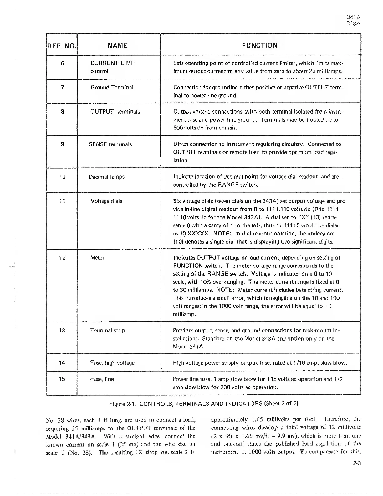
REF.
NO.
NAME FUNCTION
6
CURRENT LIMIT
control
Sets operating point of
controlled
current limiter, which
limits
max-
imum output
current
to
any value from zero to about
25
milliamps.
7
Ground Terminal Connection for grounding either positive or negative OUTPUT term-
inal
to
power line ground.
8
OUTPUT terminals Output voltage connections,
.with
both
terminal isolated from
instru-
ment case and power line ground.
Terminals
may be floated up to
500 volts dc from chassis.
9 SENSE terminals
Direct connection to instrument regulating circuitry. Connected
to
OUTPUT terminals or remote load to provide optimum load regu-
lation.
10
Decimal lamps
Indicate location of decimal point for voltage dial readout, and
are
controlled by the
RANGE
switch.
11 Voltage dials Six voltage dials
(seven
dials on the 343A) set output voltage and pro-
vide in-line digital readout from 0 to 1 1 1 1.110 volts dc
(0
to 1 11 1.
1 1
10
volts dc for the Model 343A).
A
dial set to "X"
(10)
repre-
sents
0
with a carry of 1 to the left, thus 1 1.1 1 110 would be dialed
as 10.XXXXX. NOTE: In dial readout notation, the underscore
(10)
denotes a single dial that is displaying two significant digits.
12
Meter Indicates
OUTPUT
voltage or load current, depending on setting of
FUNCTION switch. The meter
voltage
range corresponds to the
setting of the
RANGE switch. Voltage
is
indicated
on a 0 to 10
scale, with
10%
over-ranging. The meter current range
is
fixed
at 0
to 30 milliamps. NOTE: Meter current includes
beta
string current.
This introduces a small error, which is negligible on the 10 and 100
volt ranges; in the 1000
volt
range, the error will be equal to
+
1
milliamp.
13
Terminal strip Provides
output, sense, and
ground connections for rack-mount in-
stallations.
Standard on the
Model 343A
and option only on the
Model 341 A.
14 Fuse, high voltage High voltage power supply output fuse, rated
at 1/16
amp, slow blow.
15
Fuse,
line
Power
line fuse, 1 amp slow
blow for
115
volts
ac operation and 1 /2
amp slow blow for 230
volts
ac operation.
Figure
2-1.
CONTROLS,
TERMINALS AND INDICATORS
(Sheet 2 of
2)
No.
28
wires, each 3 ft
long, are
used to
connect
a load,
requiring 25
milliamps to
the OUTPUT
terminals of the
Model 341 A/343 A.
With a
straight edge,
connect the
known current on
scale
1
(25
ma)
and the
wire
size on
scale
2
(No.
28).
The
resulting
IR drop
on
Scale 3 is
approximately
1.65
millivolts per foot.
Therefore,
the
connecting
wires
develop
a
total
voltage
of 12
millivolts
(2
x 3ft x
1.65 mv/ft
=
9.9
mv), which is
more than one
and
one-half times the
published load
regulation of the
instrument at 1000
volts output. To
compensate for this.
2-3