341
A
343A
c. Set the
CURRENT LIMIT
control fully
clockwise
(25)
or to a predetermined value,
using the
proce-
dure of paragraph 2-17.
d. Set the RANGE switch
and
voltage
dials
to the
value
of the desired output voltage.
e. Set the FUNCTION
switch to ON.
f. The
output voltage
delivered to
the load will corres-
pond to the voltage
indicated on the voltage
dials.
To
monitor
output
voltage
or current, place the
FUNCTION switch
in
either
the METER VOLTAGE
or METER
CURRENT position.
2-27.
APPLICATIONS
2-28.
The Model 341 A/343
A
Voltage
Calibrators pro-
vide parameters
of stability,
accuracy, temperature
co-
efficient and response
required
by a broad range of labora-
tory and production
applications. The following
para-
graphs describe
a method of using
the instrument
as a
differential
voltmeter
and, in conjunction
with a reference
divider, as
a
precision
voltage source
with traceability to
the National
Bureau of Standards.
2-29.
OPERATION AS A DIFFERENTIAL
VOLTMETER
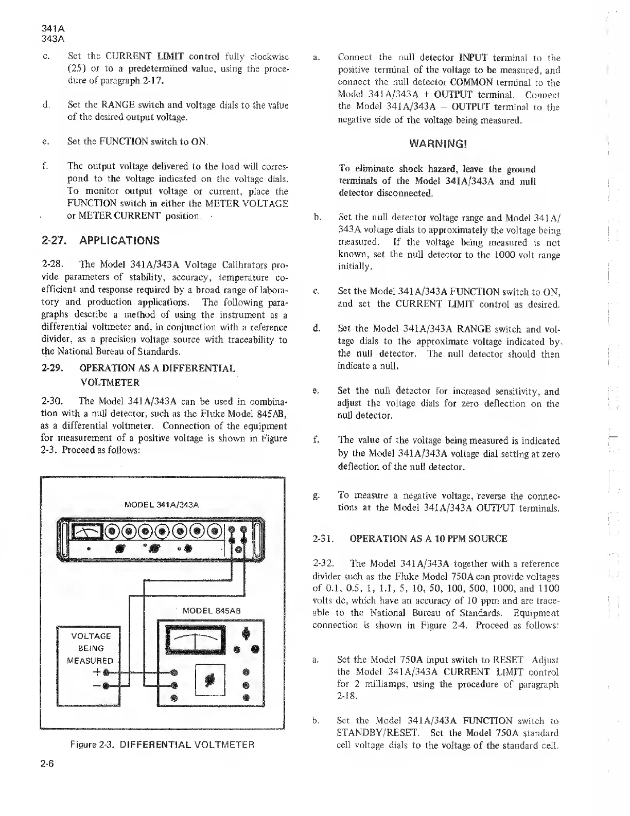
2-30.
The Model 341
A/343A can be used in
combina-
tion with
a
null
detector, such
as the Fluke Model 845AB,
as
a
differential
voltmeter. Connection
of the equipment
for measurement
of a positive voltage
is shown in Figure
2-3.
Proceed
as follows:
MODEL 34 1A/343A
Figure
2-3.
DIFFERENTIAL VOLTMETER
a. Connect the null detector
INPUT terminal
to
the
positive terminal of
the
voltage
to be
measured,
and
connect
the
null detector
COMMON terminal
to the
Model
341
A/343 A
+
OUTPUT
terminal.
Connect
the
Model
341A/343A
-
OUTPUT terminal
to the
negative
side of the voltage
being measured.
WARNING!
To eliminate
shock hazard,
leave the
ground
terminals of
the
Model
341 A/343
A and
null
detector disconnected.
b. Set
the null detector voltage
range
and Model 341
A/
343A voltage dials
to approximately
the voltage being
measured.
If the voltage
being measured
is not
known, set
the null detector
to the 1000
volt range
initially.
c.
Set the Mode]
341 A/343A
FUNCTION switch
to ON,
and
set the
CURRENT LIMIT
control as desired.
d. Set
the Model 341
A/343A RANGE
switch and vol-
tage dials
to the approximate
voltage
indicated by.
the
null detector.
The null detector
should
then
indicate
a null.
e.
Set the null
detector for increased
sensitivity,
and
adjust
the voltage dials
for zero deflection
on the
null detector.
f. The value
of the voltage being
measured
is indicated
by the Model
341 A/343A voltage
dial setting
at zero
deflection
of the
null detector.
g.
To measure
a negative voltage,
reverse
the connec-
tions at the
Model 341
A/343A OUTPUT
terminals.
2-3
1 . OPERATION AS A
1 0
PPM SOURCE
2-32.
The Model 341 A/343A together with
a
reference
divider such
as the Fluke Model 750A can provide voltages
of
0.1, 0.5,
1,
1.1,
5,
10, 50, 100, 500, 1000,
and 1100
volts dc, which have an accuracy
of
10
ppm and are trace-
able
to
the National Bureau
of Standards. Equipment
connection
is
shown
in Figure
2-4.
Proceed
as
follows:
a.
Set the
Model 750A
input
switch
to RESET Adjust
the
Model
341
A/343
A
CURRENT
LIMIT control
for
2 milliamps,
using the procedure
of paragraph
2-18.
b. Set the Model 341
A/343 A FUNCTION switch
to
STANDBY/RESET.
Set the Model
750A
standard
cell voltage
dials to the voltage
of the standard cell.
2-6