343A
STEP
VOLTAGE
DIAL
POSITION
OPERATION
|
c. OX.
0000
Record
voltage indication
within 10 uv.
d.
10.0000
Adjust
10V
LINEARITY
j
to
within 50
uv of step c.
e.
IX.0000
Record voltage
indication
within 40 uv.
f.
20.0000
Adjust 20V
LINEARITY
to within 70
uv of step
e.
9-
3X.0000
Record voltage
indication
within
40
uv.
h.
40.0000
Adjust
40V
LINEARITY
to
within 70
uv
of step
g.
i.
5X.OOOO
Record voltage
indication
within
40 uv.
j-
60.0000
Adjust 60V
LINEARITY
to within 70 uv of step i.
k.
7X.000Q
Record voltage
indication
within
40
uv.
1 .
80.0000
Adjust 80V
LINEARITY
to within
70 uv of step k.
m.
9X.0000
Record voltage
indication
within 40
uv.
n.
100-0000
Adjust 100V
LINEARITY
to within
70 uv of step
m.
Figure
4-10.
341 A
LINEARITY ADJUSTMENTS
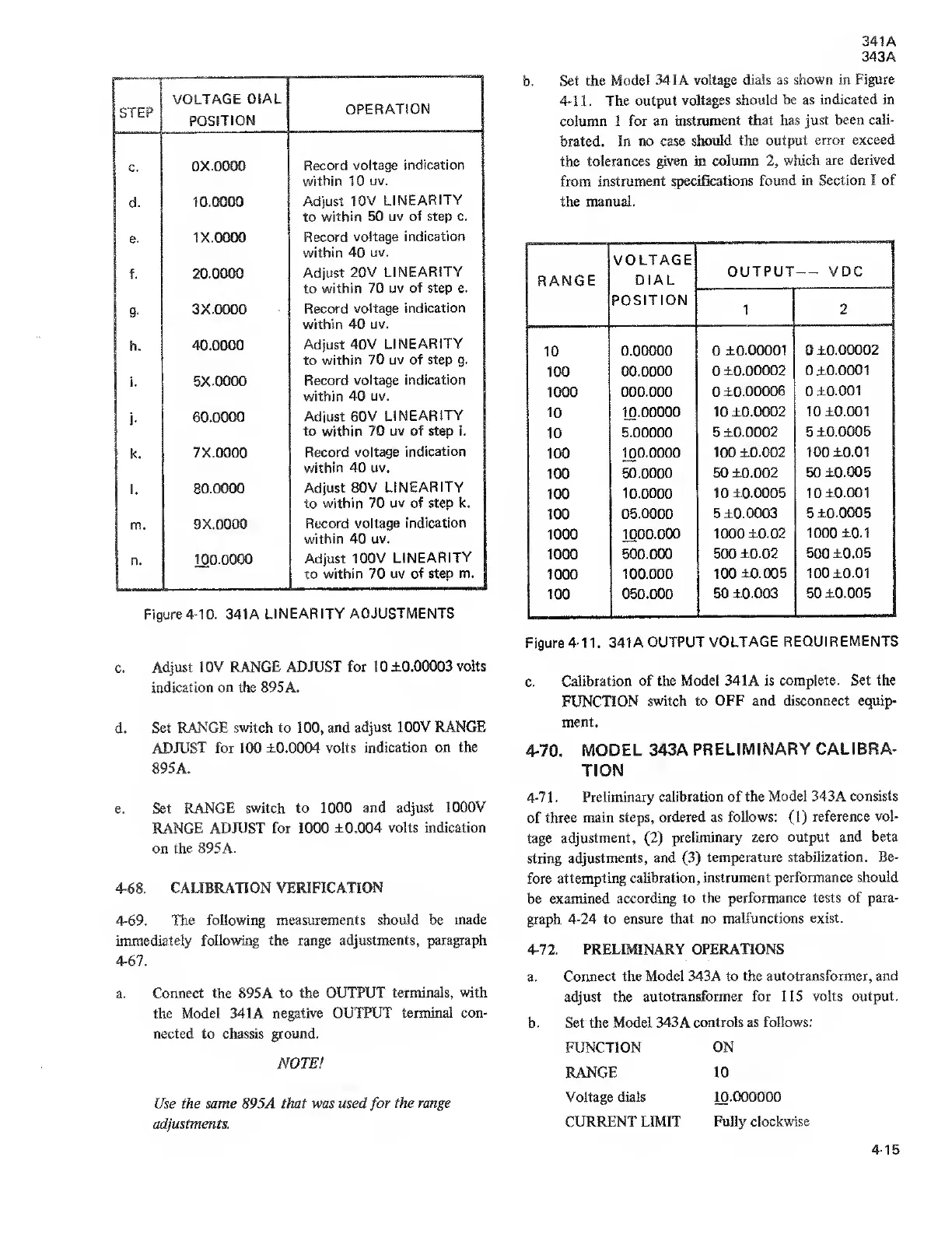
b.
Set the
Model 341A
voltage dials as
shown
in
Figure
4-11. The output
voltages should be as
indicated
in
column 1 for
an
instrument that has just
been
cali-
brated. In
no case should
the output error
exceed
the
tolerances given in column
2,
which are
derived
from
instrument
specifications found in
Section I of
the
manual.
VOLTAGE
DIAL
POSITION
OUTPUT V
DC
1 2
10
0.00000 0
±0.00001
0
±0.00002
00.0000 0
±0.00002 0 ±0.0001
1000
000.000 0
±0.00006
0
±0.001
10
10.00000
10 ±0.0002 10
±0.001
10
5.00000 5
±0.0002 5 ±0.0005
100
100.0000
100
±0.002 100 ±0.01
100
50.0000
50 ±0.002 50
±0.005
100
10.0000 10
±0.0005 10 ±0.001
100
05.0000 5
±0.0003 5 ±0.0005
m
1000.000 1000 ±0.02 1000
±0.1
500.000
500 ±0.02 500
±0.05
1000
100.000 100
±0.005 100 ±0.01
100
050.000
50 ±0.003 50 ±0.005
c.
Adjust 10V
RANGE
ADJUST
for 10
±0.00003 volts
indication on the 895 A.
d.
Set
RANGE
switch to
100,
and
adjust 100V RANGE
ADJUST for
100
±0.0004 volts
indication on the
895A.
e. Set RANGE
switch to 1000 and
adjust 1000V
RANGE ADJUST for 1000
±0.004 volts indication
on the 895 A.
4-68. CALIBRATION
VERIFICATION
4-69. The following measurements should be
made
immediately following the range adjustments, paragraph
4-67.
Connect the
895A
to the OUTPUT
terminals, with
the
Model
341 A
negative OUTPUT
terminal con-
nected to chassis ground.
NOTE!
Use
the same 895A that was used
for
the range
adjustments.
Figure
4-11.
341 A
OUTPUT
VOLTAGE
REQUIREMENTS
c.
Calibration
of the Model 341 A is
complete. Set the
FUNCTION switch to
OFF and disconnect equip-
ment.
4-70.
MODEL 343A
PRELIMINARY CALIBRA-
TION
4-7
1 . Preliminary
calibration of the
Model
343A
consists
of
three main steps,
ordered as follows:
(1)
reference vol-
tage
adjustment,
(2)
preliminary zero
output and beta
string
adjustments, and
(3)
temperature
stabilization. Be-
fore
attempting calibration,
instrument performance
should
be examined
according to
the performance tests
of
para-
graph
4-24
to ensure
that no malfunctions
exist.
4-72. PRELIMINARY OPERATIONS
a.
Connect the Model 343A to the autotransformer,
and
adjust the
autotransformer for 115 volts
output.
b.
Set the Model 343A
controls as follows:
FUNCTION
RANGE
Voltage
dials
CURRENT LIMIT
ON
10
10.000000
Fully clockwise
4-15