c. Attach all
covers.,
and allow instrument to operate
for at least 1 hour.
4-73.
REFERENCE VOLTAGE ADJUSTMENT
a. Unfasten the top
cover and slide back just
far enough
to expose REF ADJUST control
R26 and test point
TP2.
b.
Connect
the 895A differential voltmeter
to TP2,
using + SENSE as
common.
c. Adjust R26 for an
895A
indications
of 15 ±0.0001
volts dc.
d. Disconnect the
895A, and position
the top cover
so that
only
the beta
string calibration
controls are
exposed.
4-74.
ZERO OUTPUT ADJUSTMENTS
a.
Set
Model 343A
voltage
dials to zero, and connect
the negative OUTPUT
terminal to chassis ground.
b. Zero the
895A
on the
1 volt range, with null sensi-
tivity set to 100 microvolts,
then connect the
895
A
to the Model
343A OUTPUT terminals using low-
thermal copper leads.
c. Set RANGE switch to
10,
and adjust the 10V ZERO
ADJUST control for
zero
(±4
microvolts) indication
on the
895A.
WARNING*
Use only an insulated
tool for all adjustments
within the
beta string compartment.
d. Set RANGE
switch
to
100,
and adjust the 100V
ZERO ADJUST control for zero
(±10
microvolts)
indication on the
895A.
e. Set RANGE switch to
1000,
and adjust the 1000V
ZERO ADJUST control for zero
(±10
microvolts)
indication on the
895A.
4-75.
BETA STRING
LINEARITY ADJUSTMENTS
a.
Set RANGE switch to
1000,
and connect the
895
A
to
the
Model
3
43A OUTPUT terminals, with the
Model
343A
negative OUTPUT terminal connected
to chassis ground.
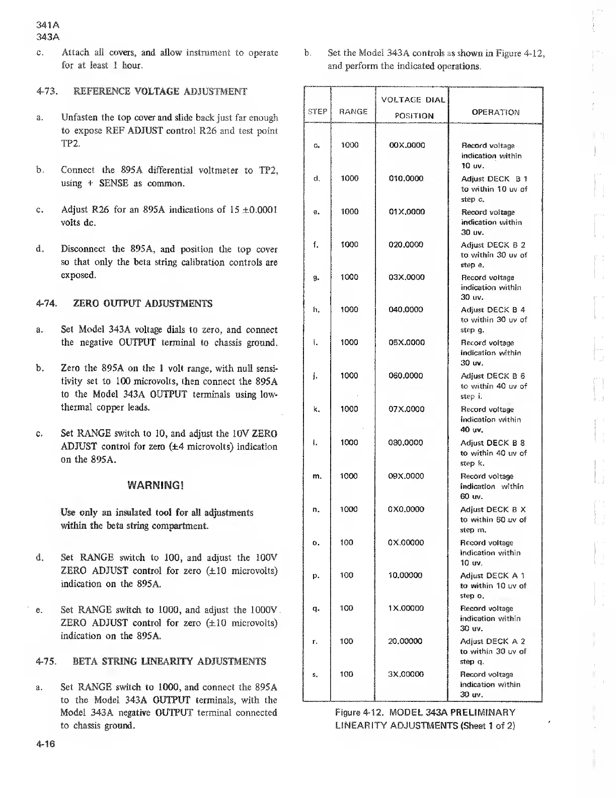
b. Set
the
Model 343A controls as shown
in Figure
4-12,
and perform the indicated operations.
STEP
RANGE
VOLTAGE
DIAL
POSITION
OPERATION
Go
1000
00 X.0000
Record voltage
indication
within
10
uv.
d.
1000
010.0000
Adjust DECK B 1
to within 10 uv of
step
c.
e.
1000 OIX.OOOO
Record voltage
indication
within
30 uv.
f. 1000 020.0000
Adjust DECK
B 2
to
within
30
uv
of
step e.
9-
1000 03X.0000 Record
voltage
indication within
30 uv.
h. 1000
040.0000
Adjust DECK B 4
to within 30 uv of
step
g.
i. 1000 OBX.OOOO Record
voltage
indication
within
30
uv.
J-
1000
060.0000 Adjust
DECK B 6
to within 40
uv of
step i.
k. 1000 07 X.0000 Record voltage
indication
within
40 uv.
1
.
1000 080.0000
Adjust DECK B
8
to within 40 uv of
step k.
m. 1000
09X.0000
Record
voltage
indication within
60 uv.
n. 1000 0X0.0000
Adjust DECK B X
to within
60
uv of
step m.
0 . 100 ox.ooooo Record voltage
indication within
10
uv.
p.
100 10.00000
Adjust DECK A 1
to within
10 uv of
step o.
q.
100 1 X.00000 Record voltage
indication within
30 uv.
r. 100 20.00000 Adjust DECK A
2
to within 30 uv of
step
q.
1
100 3X.00000 Record voltage
indication within
30 uv.
Figure 4-12. MODEL
343A PRELIMINARY
LINEARITY ADJUSTMENTS
(Sheet 1 of
2}