341
A
343A
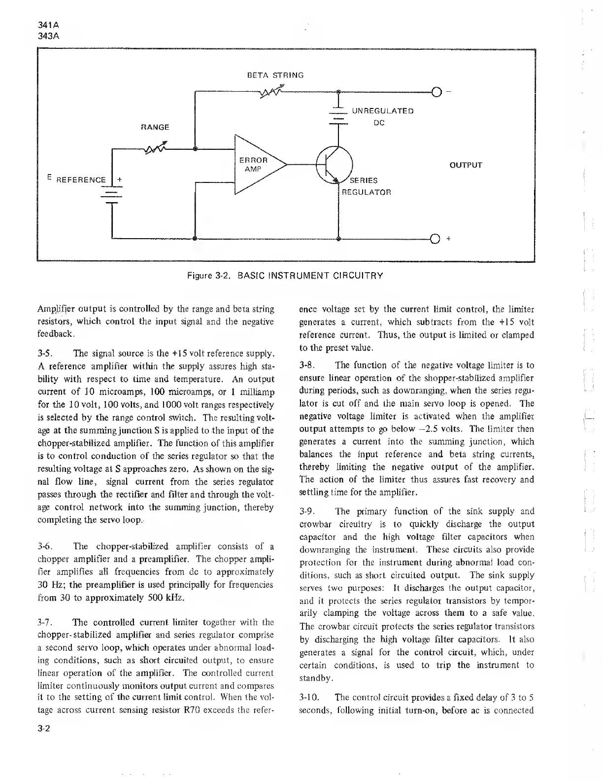
Amplifier
output is controlled by the range and beta
string
resistors, which control the input signal
and the negative
feedback.
3-5.
The signal source is the +15 volt reference
supply.
A
reference amplifier within the supply
assures
high
sta-
bility with
respect
to
time
and
temperature.
An
output
current
of 10 microamps, 100 microamps,
or 1 milliamp
for the
10
volt,
100 volts, and 1000 volt ranges respectively
is selected by the range control switch.
The resulting
volt-
age at the summing junction
S is applied to the input of the
chopper-stabilized amplifier. The function
of this amplifier
is to control conduction of the series regulator
so that the
resulting voltage at
S
approaches zero.
As shown on the sig-
nal flow line, signal current
from the series regulator
passes through the rectifier and filter
and through the
volt-
age control network into the summing
junction, thereby
completing the servo
loop.
3-6.
The chopper-stabilized amplifier consists
of a
chopper amplifier and a preamplifier. The chopper ampli-
fier amplifies all frequencies from dc to approximately
30 Hz;
the preamplifier is used principally for frequencies
from 30 to approximately 500
kHz.
3-7.
The
controlled current limiter together with the
chopper-
stabilized amplifier and series regulator comprise
a
second servo loop, which operates under abnormal load-
ing conditions, such
as
short circuited output, to ensure
linear operation
of
the amplifier. The controlled current
limiter continuously monitors output current and compares
it to
the
setting of the current limit control.
When
the vol-
tage across
current
sensing resistor
R70
exceeds the refer-
ence
voltage set
by the
current
limit control, the limiter
generates a current, which subtracts from the +15 volt
reference current. Thus, the output is limited
or clamped
to
the preset value.
3-8.
The function of the negative voltage limiter is to
ensure linear operation
of
the shopper-stabilized amplifier
during periods, such
as downranging,
when
the series
regu-
lator is cut off and the main servo loop is opened. The
negative voltage limiter is
activated
when the amplifier
output attempts to go below
-2.5
volts. The limiter then
generates a current into the summing junction,
which
balances the input reference and beta string currents,
thereby
limiting the
negative
output of the amplifier.
The action of the limiter thus assures fast recovery
and
settling time for the amplifier.
3-9. The
primary
function of the sink supply and
crowbar circuitry is to
quickly discharge the output
capacitor and the high
voltage filter capacitors when
downranging the
instrument. These circuits also provide
protection for the instrument during abnormal load con-
ditions, such as
short circuited output. The sink supply
serves
two purposes: It
discharges the output capacitor,
and it protects the series
regulator transistors
by
tempor-
arily
clamping the voltage across them to a safe value.
The crowbar circuit protects the series
regulator
transistors
by
discharging the high voltage filter capacitors. It also
generates a signal for
the control circuit, which, under
certain conditions, is
used
to trip the
instrument to
standby.
3-10. The
control circuit provides a fixed delay
of
3
to 5
seconds, following initial turn-on, before
ac is
connected
3-2