a.
Connect
the 895A
to TP7, using
+ OUTPUT as
common.
b. Set
FUNCTION
switch to ON and
RANGE switch
to 1000.
c.
Set the voltage
dials as
shown in Figure 4-8, and
verify the
voltages are as
indicated.
VOLTAGE DIALS
I
1
341
A
343A
200.000 200.0000 300 to 360
500.000 500.0000 360 to 420
700.000
700.0000 4.1
0
to 480
800.000 800.0000 450 to 520
900.000 900.0000
450 to 520
1000.000 1000.0000
470 to 540
Figure
4-8.
HIGH VOLTAGE POWER SUPPLY
OUTPUT VOLTAGES
FAULT
ANALYSIS
If the high
voltage power supply voltages
are
not correct, check diodes
CR53 and. CR54,
capacitors €55 through
€58,
and
transformer
Tl.
4-57.
BETA
STRING
4-58.
The following sequence of
tests is intended to
detect gross errors in the
beta string resistors or their
switching
patterns.
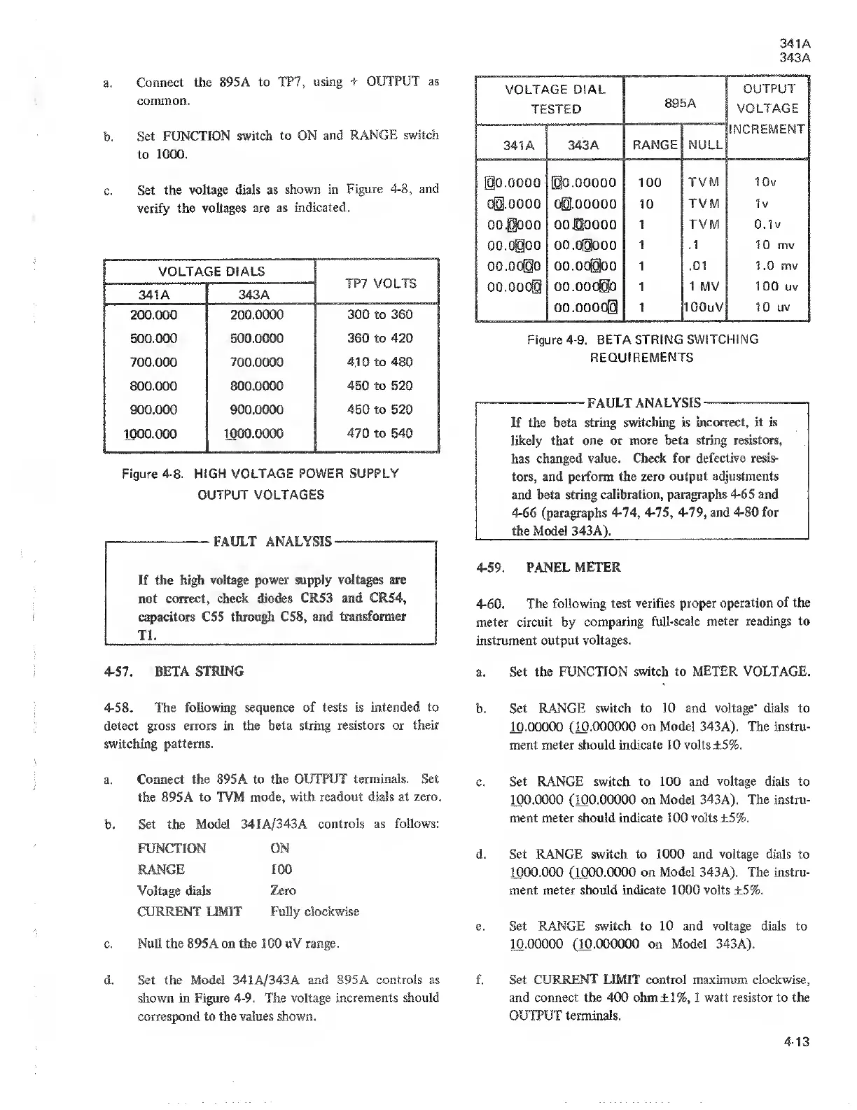
341
A
343A
VOLTAGE DIAL
TESTED
895
A
OUTPUT
VOLTAGE
INCREMENT
341
A
343
A
RANGE NULL
@
0.0000 00.00000
100
TVM IGv
Ogj.OOOG 00.00000
10 TVM 1v
oooo 0000000
1
TVM
0.1
v
00.0000
00.00000
1 .1 10 mv
00.00000
1 .01
1
.0 mv
00.00000
1 1 MV 100
uv
00.00000
1 IGOuV 10
uv
Figure
4-9.
BETA STRING SWITCHING
REQUIREMENTS
FAULT ANALYSIS
If the
beta string
switching is incorrect, it is
likely that one
or more beta string resistors,
has
changed value.
Check for defective
resis-
tors, and
perform the zero
output adjustments
and beta string
calibration, paragraphs
4-65
and
4-66 (paragraphs 4-74,
4-75, 4-79, and
4-80
for
the Model 343A).
4-59.
PANEL
METER
4-60. The following test
verifies proper
operation of the
meter circuit by
comparing
full-scale meter readings
to
instrument output
voltages.
a.
Set the FUNCTION switch
to METER VOLTAGE.
b. Set RANGE
switch to 10 and voltage' dials to
10.00000 (10.000000 on Model 343A). The instru-
ment meter should indicate 10 volts ±5%.
a.
Connect the
895A
to the OUTPUT
terminals. Set
the 895 A
to
TVM
mode, with readout dials at
zero.
b.
Set the Model 341A/343A
controls as follows:
FUNCTION
RANGE
Voltage dials
CURRENT
LIMIT
ON
100
Zero
Fully
clockwise
c. Null the 895A on the 100 uV range.
c.
Set
RANGE
switch to 100 and voltage dials to
100.0000 (100.00000 on
Model
343A).
The instru-
ment meter should indicate 100 volts ±5%.
d.
Set
RANGE switch to 1000 and
voltage
dials to
1000.000 (1000.0000
on Model
343A).
The instru-
ment meter should indicate 1000 volts ±5%.
e. Set RANGE switch to 10 and voltage dials to
10.00000 (10.000000 on Model 343
A).
Set the Model 341A/343A
and
895A
controls
as
shown in
Figure
4-9.
The voltage increments should
correspond to the
values shown.
f.
Set CURRENT LIMIT control maximum clockwise,
and connect the 400 ohm±l%,
1
watt resistor to the
OUTPUT terminals.
4-13