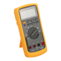
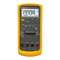
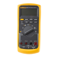
87
Users Manual
24
Use the Touch Hold mode (see item 10) to make audible
diode tests. When the test leads are placed across the
diode, a good diode or transistor junction will cause the
meter to beep (and update the display) in the forward-
biased direction and remain silent in the reverse-biased
direction. A short or resistance below about 30 kΩ will
cause a beep in both directions. If an open is detected,
the meter will remain silent in both directions.
Using the Analog Display
The analog display is easy to use and interpret. It
functions much the same as the needle on an analog
meter without the mechanical overshoot inherent in
needle movements.
The analog display is especially useful for peaking and
nulling, and observing rapidly changing inputs. The analog
display response time is fast, and it can be used to make
approximate adjustments quickly. The 4000-count digital
display can then be used for final adjustment.
The analog display can also be used for limited diagnostic
purposes. In situations where rapidly fluctuating signal
levels make the digital display useless, the analog display
is ideal. Like the needle on a Volt-ohm-milliammeter
(VOM), the analog display excels at displaying trends, or
slowly changing signals. Many diagnostic routines using
the analog display require practice. You will usually be
looking for good or bad signal patterns that occur over
some span of time. Noisy resistance measurements, for
instance, create such patterns. Therefore, familiarity with
analog display response and movement is necessary to
accurately interpret a signal pattern. Compare the analog
display response when making measurements on a unit
known to be good, to the analog display response when
making measurements on a faulty unit.
Using the MIN MAX Recording Mode
The MIN MAX Recording mode can be used to catch
intermittents and turn on or turn off surges, verify
performance, measure while you are away ("baby sit"), or
take readings while you are operating the equipment
under test and cannot watch the meter. The audible Min
Max Alert indicates when a new minimum or maximum
value has been recorded.
You can select either a 100 millisecond, 1 millisecond
(Peak), or 1 second (high accuracy) "response time" for
recording minimum and maximum readings. The response
time is the length of time an input must stay at a new
value to record the full change.
The 100 millisecond response time is best for recording
power supply surges, inrush currents, and finding