Ut7iiA.
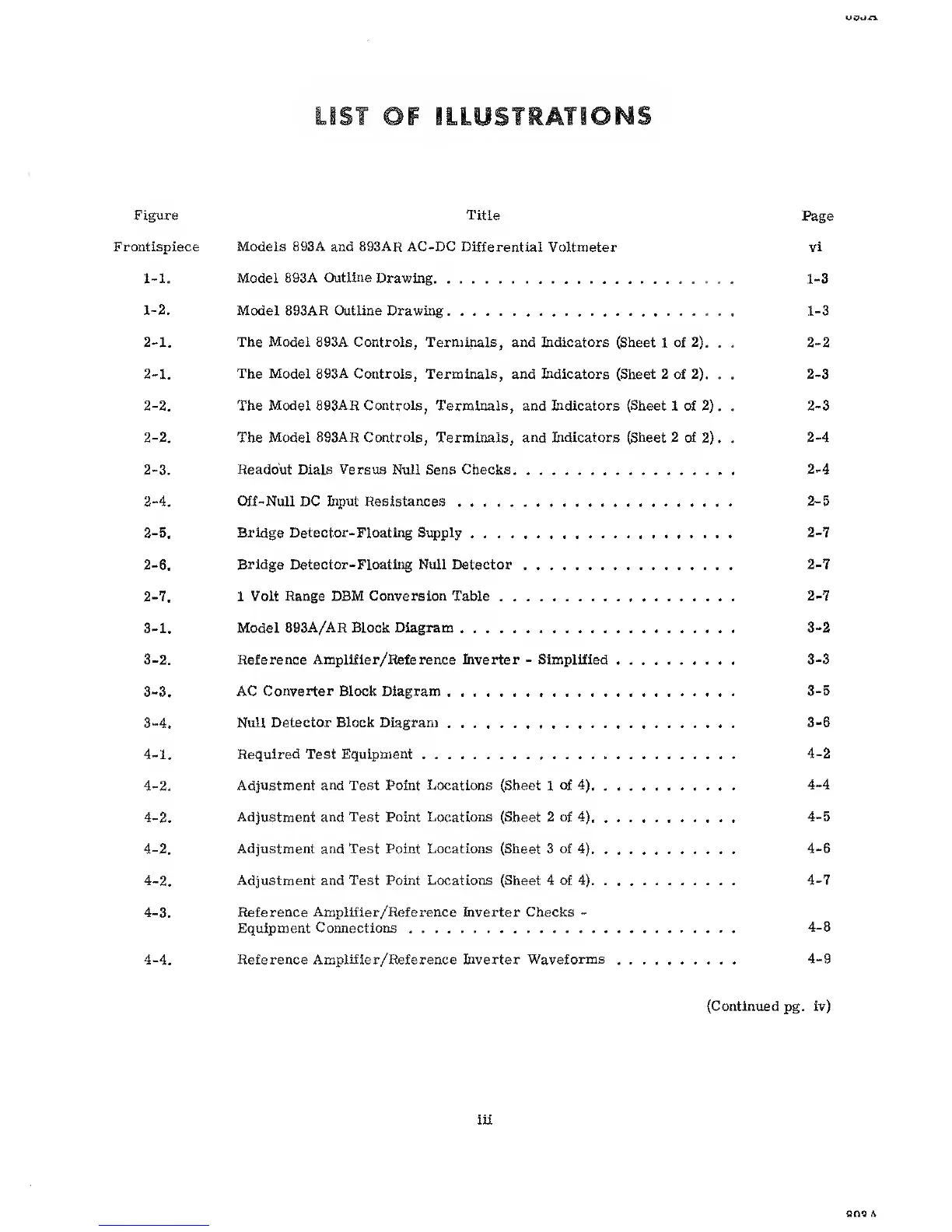
IONS
Figure
Title
Page
Frontispiece
Models 893A
and 893AR AC-DC Differential
Voltmeter
vi
1-1.
Model
893A Outline
Drawing.
1-3
1-
2.
Model 893AR Outline Drawing 1-3
2-
1.
The Model 893A Controls, Terminals,
and
Indicators
{Sheet
1
of
2). . .
2-2
2-1.
The
Model
893A
Controls, Terminals, and Indicators (Sheet
2 of
2).
.
.
2-3
2-2. The Model 893AR Controls, Terminals,
and
Indicators (Sheet
1 of
2) . .
2-3
2-2. The Model 893AR Controls, Terminals, and Indicators (Sheet
2
of
2) . .
2-4
2-3.
Readout Dials
Versus Null Sens Checks
2-4
2-4.
Off-Null DC
Input
Resistances
2-5
2-5. Bridge Detector-Floating Supply
2-7
2-6. Bridge Detector-Floating Null Detector
2-7
2-
7.
1
Volt Range DBM Conversion Table
2-7
3-
1.
Model
893A/AR
Block
Diagram 3-2
3-2.
Reference
Amplifier/Reference Inverter
-
Simplified
3-3
3-3. AC Converter Block Diagram
3-5
3-
4.
Null Detector Block Diagram 3-6
4-
1.
Required Test Equipment
4-2
4-2. Adjustment and Test Point Locations (Sheet
1
of
4)
4-4
4-2.
Adjustment and Test Point Locations (Sheet
2
of
4)
4-5
4-2. Adjustment and Test Point Locations (Sheet 3 of
4)
4-6
4-2. Adjustment and
Test
Point
Locations
(Sheet
4 of
4). .
4-7
4-3. Reference Amplifier/Reference Inverter Checks
-
Equipment
Connections
4-8
4-4. Reference Amplifier/Reference
Eiverter Waveforms
4-9
(Continued
pg.
iv)
iii
aao A