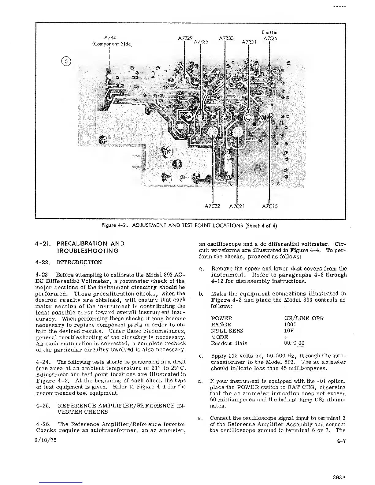
Figure
4-2.
ADJUSTMENT AND TEST
POINT
LOCATIONS (Sheet 4
of
4}
4-21.
PRECALIBRATION AND
TROUBLESHOOTING
4-22.
INTRODUCTION
4-23.
Before attempting to calibrate the Model 893 AC-
DC
Differential Voltmeter,
a
parameter check of the
major
sections
of
the instrument circuitry
should be
performed. These precalibration checks,
when
the
desired results
are
obtained, will ensure
that
each
major
section of the instrument is
contributing
the
least
possible error
toward overall instrument inac-
curacy.
Wlien
performing these checks it
may
become
necessary
to replace
component parts in order to ob-
tain the desired
results. Under
these circumstances,
general
troubleshooting of
the circuitry is necessary.
As
each
malfunction is corrected,
a
complete recheck
of
the
particular circuitry
involved is also necessary.
4-24. Hie following tests should be
performed in
a
draft
free area at an
ambient
temperature
of
21°
to 25°C.
Adjustment and
test point locations are
illustrated
in
Figure
4-2.
At the
beginning
of
each check the type
of test
equipment is given. Refer
to Figure
4-1
for
the
recommended test
equipment.
4-25. REFERENCE
AMPLIFIER/REFERENCE IN-
VERTER CHECKS
4-26.
The Reference Amplifier/Reference Inverter
Checks require
an autotransformer,
an ac ammeter,
2/10/75
an
oscilloscope and
a dc
differential
voltmeter. Cir-
cuit
waveforms are illustrated in Figure
4-4.
To per-
form
the checks,
proceed
as
follows:
a. Remove
the upper
and lower dust covers from the
instrument. Refer to paragraphs
4-8
through
4-12
for disassembly instructions.
b. Make the equipment
connections illustrated in
Figure
4-3
and place the Model 893
controls
as
follows:
POWER
ON/LINE
OPR
RANGE
1000
NULL SENS
lOV
MODE
+
Readout dials
00.
0 00
c.
Apply 115 volts ac,
50-500 Hz, through the auto-
transformer
to the Model 893. The ac
ammeter
should indicate less than 45
miliiaraperes.
d. If your instrument is equipped with the
-01
option,
place the POWER switch to BAT CHG, observii^
that the ac ammeter
indication
does not exceed
60 milliamperes and
the
ballast lamp DSi illumi-
nates.
e.
Connect the oscilloscope
signal input to terminal 3
of the Reference Amplifier Assembly and connect
the
oscilloscope ground
to terminal
6 or 7. The
4-7
89.3 A