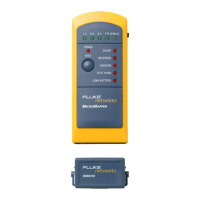
MICROMAPPER
TM
ENGLISH - 5
MICROMAPPER
Tests
1. Slide the switch on the right side to the Cable
position to turn MICROMAPPER on.
2. Connect one end of the cable to be tested to the
MICROMAPPER's RJ45 jack.
3. Connect the other end of the cable to the MICROMAP-
PER Remote's RJ45 jack.
4. Press (TEST) to view the results.
5. The horizontal LEDs indicate the cable's integrity
status.
Green: Pair or Shield is good
Green flashing: Pair or Shield is faulty
No light: Pair is open or cable is not shielded
6. The vertical LEDs indicate the wiring faults and a low
battery status. Wiring faults are: SHORT, RE-
VERSED, MISWIRE, SPLIT PAIRS.
7. To find out a fault on a specific pair, use
MICROMAPPER's diagnostic feature.
8. Press and hold (TEST) for more than 2 seconds.
MICROMAPPER will scan each pair and the shield
pausing and flashing each green LED separately. If a
faulty pair is detected, the corresponding fault status
will blink in red.
Note: Push the Remote Terminator onto the MicroMap-
per until it snaps into position. This configuration
allows you to conveniently test patch cables.