ScopeMeter® Test Tool 190 Series II
Users Manual
A
B
C
D
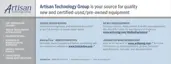
Figure 39. Parasitic capacitance between probes,
instrument and environment
Note:
Parasitic capacitances such as shown in Figure
39, 41 and 43 can cause ringing on the signal.
Ringing can be limited by adding a ferrite bead
around the probe cable.
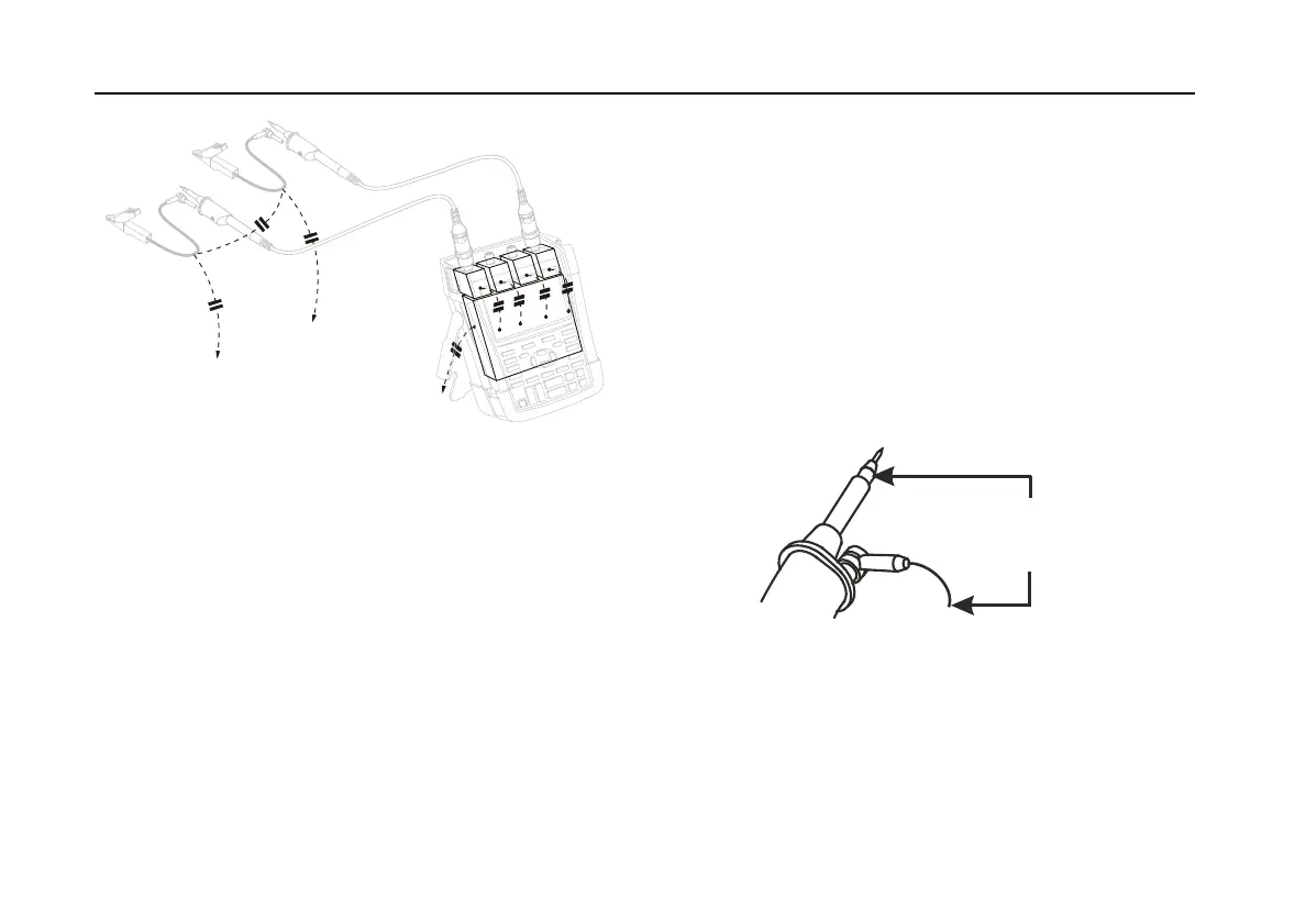
Warning
To avoid electrical shock, always use the
insulation sleeve (Figure 1, item e) or the
hook clip when using the probe reference
(ground) lead. The voltage applied to the
reference lead is also present on the ground
ring near the probe tip as shown in Figure 40.
The isolation sleeve avoids the risk of
accidently interconnecting the reference
contact of multiple probes when groundleads
are connected or short-circuiting any circuitry
via the bare ground ring..
6$0(
327(17,$
Figure 40. Probe Tip
 Loading...