Using the Scope and Meter
Input Connections
Input Connections
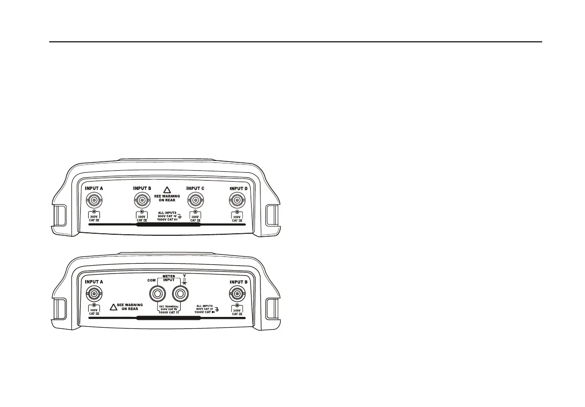
/RRNDWWKHWRSRIWKHWHVWWRRO7KHWHVWWRROKDVIRXU
VDIHW\%1&MDFNVLJQDOLQSXWVPRGHOV±[[RUWZR
VDIHW\%1&MDFNLQSXWVDQGWZRVDIHW\PPEDQDQDMDFN
LQSXWVPRGHOV[[6HH)LJXUH
,VRODWHGLQSXWDUFKLWHFWXUHDOORZVLQGHSHQGHQWIORDWLQJ
PHDVXUHPHQWVZLWKHDFKLQSXW
ALL INPUTS ISOLATED
!
ALL INPUTS ISOLATED
!
Figure 5. Measurement Connections
Making Input Connections
7RPDNHVFRSHPHDVXUHPHQWVFRQQHFWWKHUHGYROWDJH
SUREHWRLQSXW$WKHEOXHYROWDJHSUREHWRLQSXW%WKH
JUH\YROWDJHSUREHWRLQSXW&DQGWKHJUHHQYROWDJHSUREH
WRLQSXW'&RQQHFWWKHVKRUWJURXQGOHDGVRIeachYROWDJH
SUREHWRLWVownUHIHUHQFHSRWHQWLDO6HH)LJXUH
)RU0HWHUPHDVXUHPHQWVUHIHUWRWKHDSSOLFDEOHVHFWLRQLQ
WKLVFKDSWHU
Warning
To avoid electrical shock use the insulation
sleeve (Figure 1 item e)) if you use the probes
without the hook clip or the ground spring.
Notes
To maximally benefit from having
independently isolated floating inputs and to
avoid problems caused by improper use,
read Chapter 6: “Tips”.
For an accurate indication of the measured
signal, it is necessary to match the probe to
the test tool’s input channel. See section
‘Calibrating the voltage Probes’ in Chapter 7.
 Loading...