TiR2,TiR3,TiR4,Ti40,Ti45,Ti50,Ti55
Users Manual
2-4
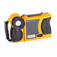
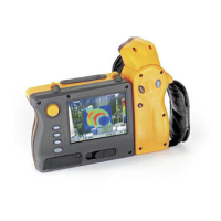
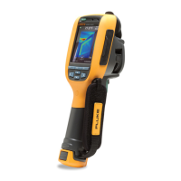
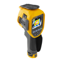
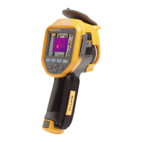
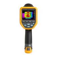
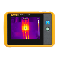
Table 2-1. Camera Parts – Descriptions
Item Description
A
Mouse controller – Used to control the pointer position in images and
text menus.
B
E select button – Performs mouse click, or “enter” function, for
the pointer.
C
F Menu button – Used to access display screen menus. Note: Tap
F once and a popup menu appears.
D
A Programmable function button – Can be programmed to
perform different menu functions, see Programming Function Buttons
later in this Chapter.
E
B Programmable function button – Can be programmed to
perform different menu functions, see Programming Function Buttons
later in this Chapter.
F
C Programmable function button – Can be programmed to
perform different menu functions, see Programming Function Buttons
later in this Chapter.
G
D Power on or off button – Used to power camera on and off and
to place the camera in a low-power standby mode to conserve battery
power.
Solid green = power is on; Blinking green = standby mode enabled.
H
Auxiliary power port – Connection port for AC to DC power adapter.
I
Reset – Hidden switch to reset camera. Can be accessed with a paper
clip. See, “Appendix B – Troubleshooting”.
J
Battery latch – Used to remove battery.
K
Liquid Crystal Display (LCD) screen – Sunlight-readable color display
for viewing images and accessing camera menu functions.
L
G LEVEL & SPAN button – Used to rescale the color palette to the
maximum and minimum temperatures in current image and to adjust IR
Fusion level.
M
Infrared lens – Germanium lens with manual focus.