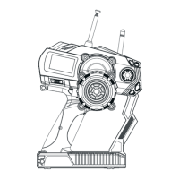
Propeller
Optical rotation
speed telemetry
module
12.06 FS-ATM01 Temperature telemetry module connection setup
LE
D
FS-SP
D02
SPEED
2
OUT
IN
Magnetic
12.05 FS-APD02 RPM Telemetry (optical) module setup
Magnet
Sensor
12.07 FS-AVT01
(Pic 12.6)
(Pic 12.7)
(Pic 12.8)
(Pic 12.9)
1. Insert one end of standard 3 PIN plug into “OUT” port of temperature module, and insert the other end into “IN” port of
receiver or other sensor, as shown in the picture 12.8 .
2. Adhere temperature sensor to proper place (such as motor and battery) tightly by sponge double stick.
3. Switch on transmitter and receiver. “Temperature 1:25.0℃” will be shown in receiver window in display screen, which means
installation is successful, and 25.0℃ is the temperature collected.
1. Insert one end of standard 3 PIN plug into “OUT” port of external voltage module, and insert the other end into “IN” port
of receiver or other sensor, as shown in the picture 12.9.
2. Switch on transmitter and receiver. “Ext.voltage4:12.40V” will be shown in receiver window in display screen, which
means the installation is successful.
3. Insert red and black contact pin into battery port respectively. The red one is positive pole and the black one is
negative pole.as shown in the picture 12.9“Ext.voltage4:12.40V” is shown in the receive widow in display screen,
which means the tested voltage is 12.40V.
Notice: The polarity of red and black line can not be reversed, or the receiver will be damaged.
Notice: Be sure the IN and OUT ports are connected correctly. Improper connections
will cause the transmitter to be unable to distinguish between telemetry modules.
1. Connect one end of the standard 3 PIN plug to the "out" port of the speed telemetry module
and the other end to the "in" port of the receiver or the previous sensors “in” port as shown in
the picture 12.6.
2. As shown in the picture 12.7: Affix the sensor and the reflection decals on the flat surface of
the side of any rotating part. Keep decals flat and perpendicular to the sensor. Maintain
sufficient safety distance between the sensor and the decals to avoid any damage.
3. Switch on the transmitter and the receiver. “Motor speed 2: 0RPM” will be displayed in the
main screen. The speed displayed will follow the speed of the rotating part monitored by the
rotation speed sensor, indicating a successful installation.
This function allows the user to monitor turning speed via the transmitter. This is a very
useful function when determination of turning speed is required
This function allows the user to monitor the temperature of important operating parts of the system.
This will ensure that the user can be aware of any severe temperature changes which would adversely affect
system operation. The system will automatically set an alarm if the temperature is outside of safe operating norms
This function allows the user to monitor the battery voltage of the system. This will ensure that the user can beaware of
any severe voltage changes which would adversely affect battery operation. The system will automat-ically set an alarm if
the voltage is outside of safe operating norms
Function Details:
Operation instruction:
Function Details:
Operation instruction:
Function Details:
Operation instruction:
External voltage telemetry module connection setup
A
A
A
517
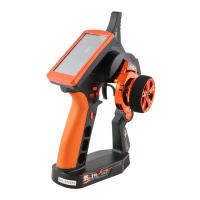
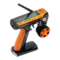
Digital proportional radio control system

 Loading...