Make sure that the impeller rotation is correct. For more information, see Check the
impeller rotation (page 36).
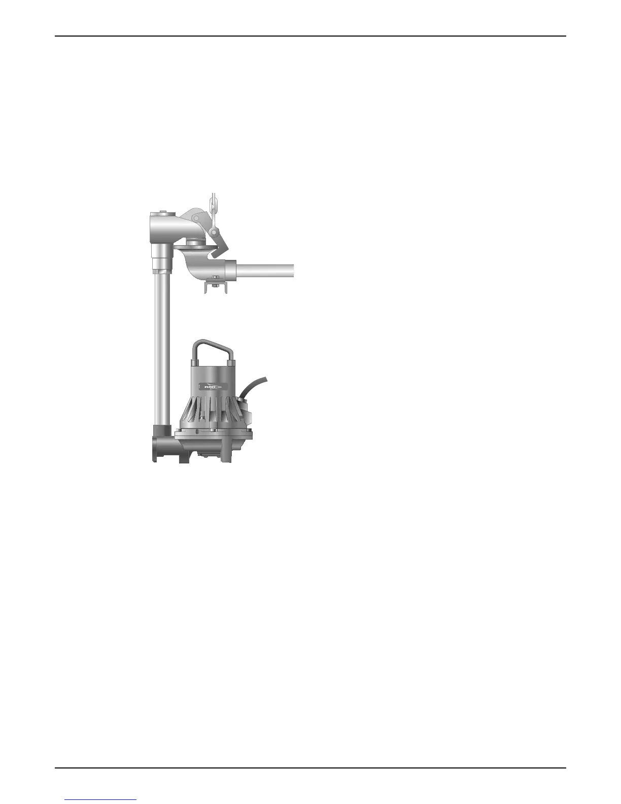
4.1.5 Install with H-installation
This installation is only applicable for the following versions:
• 172
• 891
In the H-installation, the pump is installed with a permanent, quick-connection, suspended
arrangement that incorporates an integral non-return valve. The pump is intended to
operate completely or partially submerged in the pumped liquid. These requirements
and instructions are for H-installations that comply to the dimensional drawing.
Figure 8: H-installation
These items are required:
• Discharge connection
• Pipe
1. Run the cable so that is has no sharp bends, is not pinched, and cannot be sucked into
the pump inlet.
2. Fit the pipe and connect the discharge connection.
3. Lower the pump into the sump.
4. Make sure that the pump is hanging just above the sump bottom.
5. Connect the motor cable and the starter and monitoring equipment according to the
separate instructions.
Make sure that the impeller rotation is correct. For more information, see Check the
impeller rotation (page 36).
Clean all debris from the sump before you start the pump.
4.1.6 Install with X-installation
In the X-installation, the pump has no pre-determined mechanical connection. The flange
is drilled.
4 Installation
22 Flygt 3085 Installation, Operation, and Maintenance Manual