Replace any defective equipment.
4.2.4 Cable charts
Description
This topic contains general connection information. It also provides cable charts that show
connection alternatives for use with different cables and power supply.
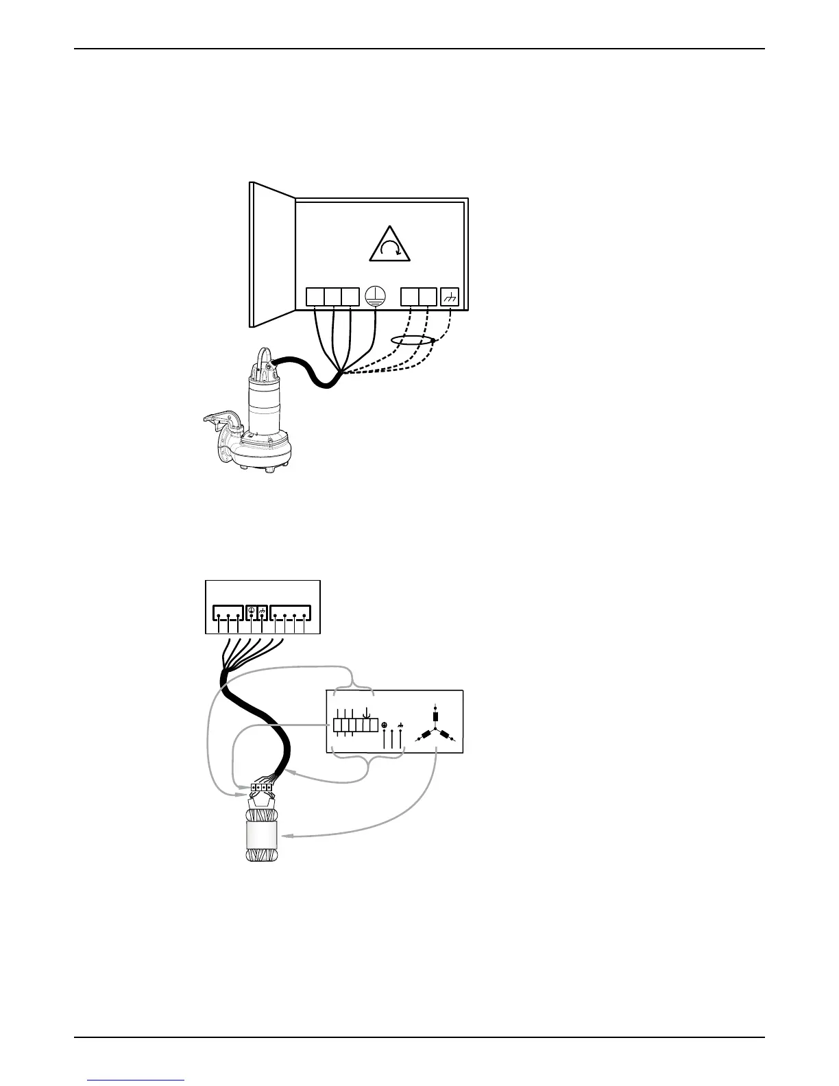
WS000509E
L2
L3L1
L1
L3L2
T1
T2
Figure 11: Phase sequence
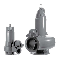
Connection locations
The
figures in this section illustrate how to interpret the connection strip symbols.
1
2
3
4
L1 L2 L3
T3 T4T1 T2
U1
V1
W1
U2
W2
V2
U1
V1
W1
W2
U2
V2
U1
V1
W1
GC
W2
U2
V2
L1
L2
L3
*YE
GN/YE
WH
L1
U1
U2
W2
V2
W1
V1
L3
L2
WS004133D
1. Stator leads
2. Terminal board
3. Power cable leads
4. Stator (internal connection illustrated)
4 Installation
28 Flygt 3085 Installation, Operation, and Maintenance Manual