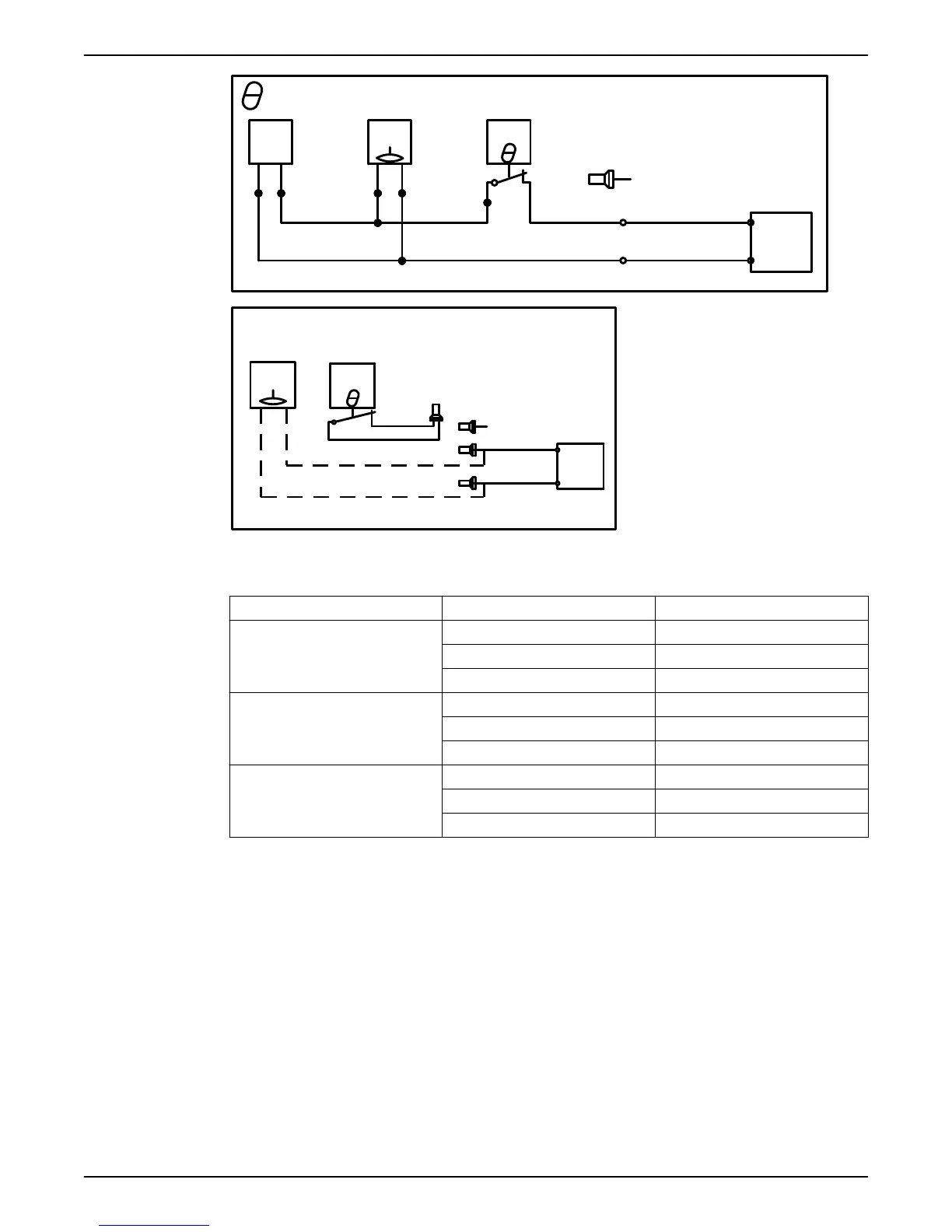
+ FLS+CLS
CLS
FLS
TC
Max 12 V
BK
BN
BU
BU
WH
6
YE
RD/BN
BU
RD/BN
WH/YE
T1
Control leads
BU
T1/*OG/4
+7
Mini
BK
T2
-5
CAS
*SUBCAB AWG
T2/*BU/5
FLS
Temp > 40° T1,T2 thermal
FLS
TC
contacts not connected
WH/YE
6
WH/YE
Control leads
BU
T1/*OG/4
+7
Mini
-5
CAS
BU
T2/*BU/5
*SUBCAB AWG
WS004131A
Sensor connection characteristics
The values have a 10 % tolerance.
Sensors Value (mA) Definition
FLS and thermal contact 0 Overtemperature
7.8 OK
36 Leakage
CLS and thermal contact 0 Overtemperature
5.5 OK
29 Leakage (5 seconds delay)
CLS, FLS and thermal contact 0 Overtempterature
13.3 OK
36–42 Leakage (0/5 seconds delay)
4.3 T-installation: Bleed air before starting pump
1. Open valve D and bleed out the air. See the following figure.
4 Installation
Flygt 3085 Installation, Operation, and Maintenance Manual 35