L1 L2 L3
T3 T4T1 T2
43
21
5
10
8
CLS
6
FLS
7
FLS 10
11
9
WS004134A
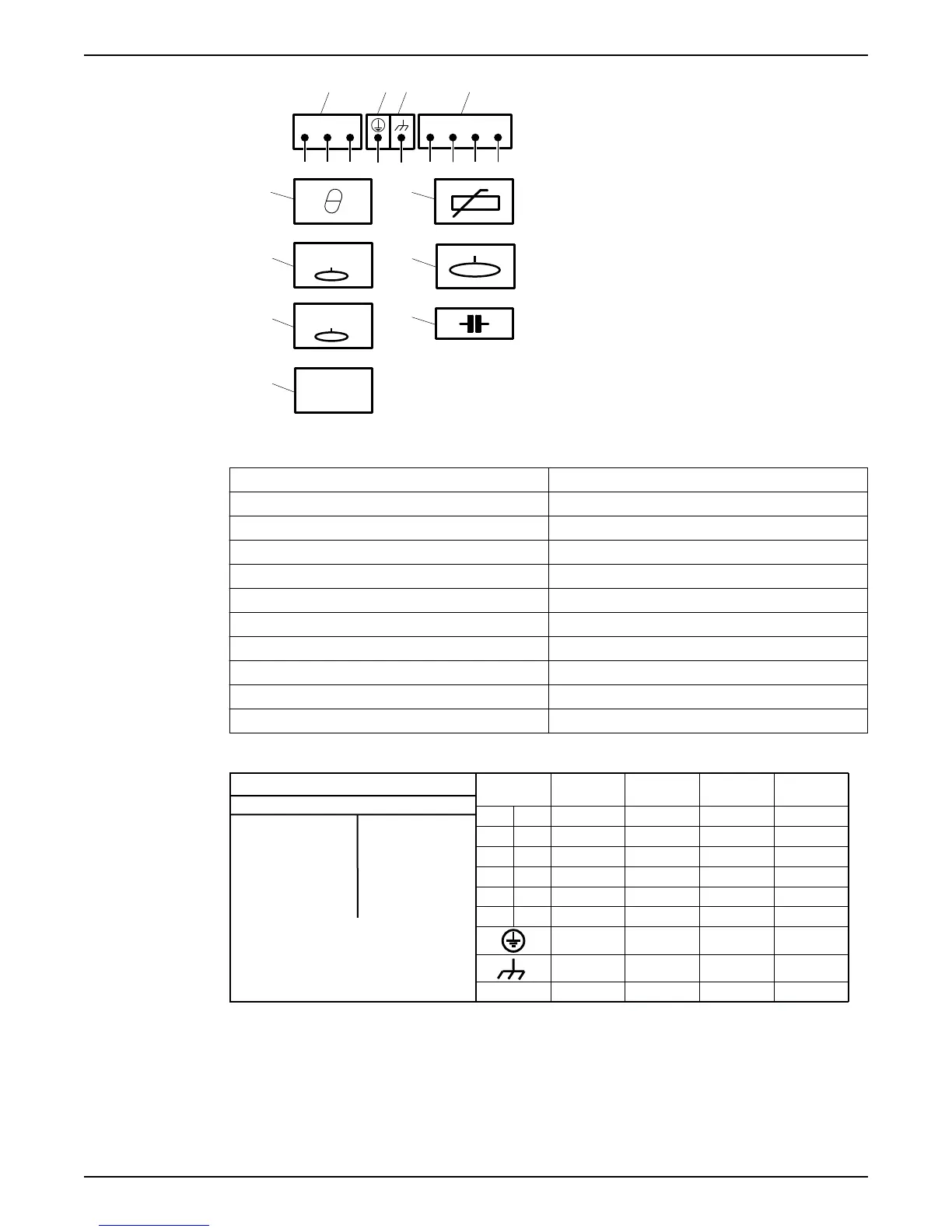
1. Starter equipment and mains leads (L1, L2, L3)
2. ground (earth)
3. Functional ground
4. Control leads (T1, T2, T3, T4)
5. Thermal contact
6. FLS
7. FLS 10
8. CLS
9. Thermistor
10.Level sensor
11.Capacitor
Color code standard
Code Description
BN Brown
BK Black
WH White
OG Orange
GN Green
GNYE Green-Yellow
RD Red
GY Grey
BU Blue
YE Yellow
4.2.4.1 Colors and markings of leads
772 17 00
( 6)
REV
COLOUR STANDARD
BN=Brown
BK=Black
WH=White
OG=Orange
GN=Green
GN/YE=Green-Yellow
RD=Red
GY=Grey
BU=Blue
YE=Yellow
STATOR LEADS
U1,U5 RD
U2,U6 GN
V1,V5 BN
V2,V6 BU
W1,W5 YE
W2,W6 BK
T1,T2 WH/YE
*SUBCAB AWG
* * Ground Conductor is stranded around cores
GC=Ground Check
Colours and marking of main leads
Motor connection
1 L1 BK 1 BN RD BN
2 L2 BK 2 BK BK BK
3 L3 BK 3 GY WH GY
L1 BK 4
- - -
L2 BK 5
- - -
L3 BK 6
- - -
GN/YE GN/YE GN/YE
**Screen/PE
from cores
Screen (WH) Screen (WH)
-
Screen (WH)
Mains
1~ 3~
SUBCAB 7GX
Screenflex 7GX
SUBCAB 4GX
Screenflex 4GX
SUBCAB AWG
SUBCAB
Screened
GC
- -
YE
-
WS004125B
For markings on sensor leads, see Sensors connection (page 34).
4.2.4.2 Connections included
• 3-phase connection (page 30)
• 1-phase connection (page 32)
• Sensors connection (page 34)
• Screened cable connection (page 33)
4 Installation
Flygt 3085 Installation, Operation, and Maintenance Manual 29