Colors and markings on power cables
Table 12: Colors or markings on the main leads
Mains
Color of cable lead
SUBCAB SUBCAB AWG
NTSCGEWTOEUS
(marking)
L1 cable lead
Brown Red
Black (L1)
L2 cable lead Black Black Black (L2)
L3 cable lead Grey White Black (L3)
Earth PE or ground cable lead Green/Yellow Green/Yellow Green/Yellow
Ground check GC cable lead — Yellow —
Table 13: Color of stator leads. (Cables up to 1.1 kV. Not valid for 1.2–10 kV cables.)
Stator leads Color
U1 Red
V1 Brown
W1 Yellow
U2 Green
V2 Blue
W2 Black
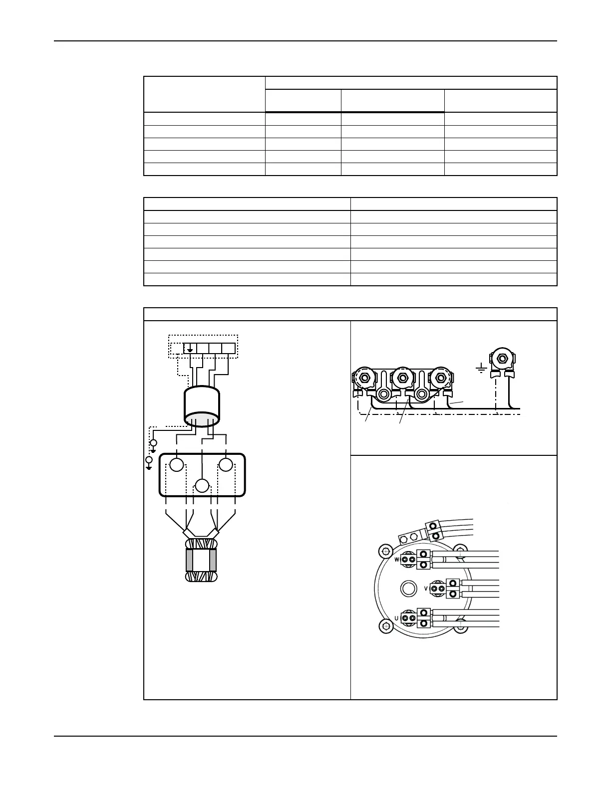
Drive units up to 1.1 kV
D-connection, 3-pole terminal, 1 or 2 cables
SUBCAB
GC
GC
V2 W1
W2
U1
V1
V
W
U
U2
L2L3L1
10002d
D
L2 L3L1
GC
3~
Figure 23: Schematic diagram
This cable chart shows the connection for drives
units in the 6X5 series.
Figure 24: Drive units 605/615, 665/675
This cable chart shows the connection for drive
units in the 8X5 and 9X5 series; also drive units 7X5
with large junction box (see Connection houses (junction
boxes) in 7X5 drive units (page 66)).
Figure 25: Drive units 805/815, 835/845,
865/875, 885/895; 905/915, 935/945, 965/975;
7X5 with large junction box
Installation
C3300/6x5, C/R3231, C3240, C3306, C3312, C3351, C3356, C3400, C3501, C3531, C3602, C3800 Installation,
Operation and Maintenance Manual
59