www.fmiproducts.com
124387-01D20
CONNECTING FIREPLACE TO GAS
SUPPLY
WARNING:Gaslinehookup
should be done by your gas
supplier or a qualied service
person.
CAUTION:Donotkinkex-
iblegasline.
CAUTION:Compoundsused
onthreadedjointsofgaspiping
shallberesistanttotheaction
of Liqueed Petroleum (LP or
propane)andshouldbeapplied
lightlytoensureexcesssealant
does not enter the gas line.
INSTALLATION
Continued
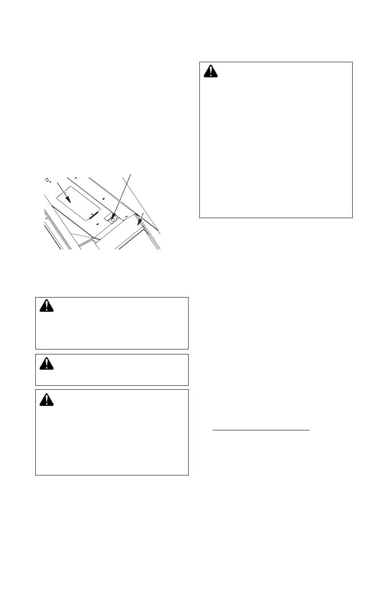
Rating
Plate
Hole for Screen
Rod
Leading Bricks
Figure 30 - Installing Fireplace Screen
INSTALLING SCREEN
1. Slide round end of screen rod into rings at
top of screen. Attach one push-on nut to end
of rod before attaching last ring of screen.
2. Insert the round end screen rod into hole
on the left and right side of smoke shelf
(Figure 30).
3. Mount at end of screen rod with #10 x 5/8"
to center of smoke shelf.
4. Install other screen rod in same manner.
WARNING: All gas piping
andconnectionsmustbetested
forleaksaftertheinstallationis
completed.
After ensuring that gas valve
ison,applyacommercialleak
detection solution to all con-
nectionsandjoints.Ifbubbles
appear, leaks can be detected
and corrected.
Donotuseanopenameforleak
testing and do not operate any
applianceifaleakisdetected.
Complete your gas installation by connect-
ing incoming gas line with exible gas line
attached to the log/burner module. Secure
tightly with wrench but DO NOT OVER-
TIGHTEN.
Apply pipe joint sealant lightly to male NPT
threads. This will prevent excess sealant from
going into pipe. Excess sealant in pipe could
result in clogged replace valves.
InstallationItemsNeeded
• 5/16" hex socket wrench or nut-driver
• sealant (resistant to propane/LP gas, not
provided)
1. Route exible gas line supplied with log/
burner module through the large hole on
the rebox bottom to the incoming gas line
(Figure 25, page 18).
2. Attach exible gas line from gas supply to
control valve (see Figure 31, page 21).
3. Check all gas connections for leaks. See
Checking Gas Connections, page 22.
 Loading...