11
For specific servicing instructions, see the relevant sections.
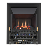
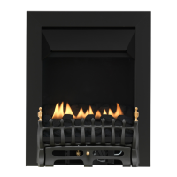
Remove the firefront and place to one side. Remove the ceramic components. Gently clean in the open air. Be careful not to create
dust from the coals. Where necessary replace damaged components with genuine spares. Seal scrap ceramic components in plastic
bags and dispose at proper refuse sites as directed.
Re-fit the coals by referring to the relevant section of these instructions.
Remove the decorative front. Remove the ceramics and the data/control plate and place safely aside.
Slide control models - disconnect the slide control mechanism by removing the M4 nut on the slide control linkage.
Remove the two screws securing the tray legs to the firebox. Pull tray forward slightly and lift away.
Refitting is the reverse of above, being sure to engage the tray location lugs on the shelf at the rear of the firebox.
Remove the burner unit as previously described. The pilot unit can be removed by withdrawing the tubing nut, the thermocouple nut on
the rear of the valve, and the two securing screws, and lifting away. Remove the tubing nut from the valve end of the pilot pipe, and blow
through to dislodge any debris.
Remove the two tubing nuts on the ends of the gas pipe to the injector elbow and blow clear. Release the screw through the supporting
leg and lift assembly clear. The injector pipe can now be checked for debris. Remove the nut retaining the injector elbow. Blow through
the elbow to remove any debris.
Manual control models only : The valve is not field serviceable, apart from the pilot filter. Remove the control knob by pulling it forwards,
then remove the largest of the three screws on the face of the valve. Slide the filter out and clean away any debris that may have accu-
mulated. The filter element should also be blown clean. This component should not require replacement, however if signs of deteriora-
tion are evident then a genuine spare part must be used. If a large amount of debris is present in the filter then the pipework and con-
trol should be thoroughly cleaned before re-assembly.
Remove the burner unit as in relevant section and pilot unit as described.
Clean the pilot assembly with a soft brush and blow through. Check the aeration holes are free of any dirt or lint. Clean thoroughly
internally, the connection can be removed from the base of the pilot unit using two spanners to make cleaning easier. Do not damage
or try to remove the pilot injector. The unit is factory set and the only check necessary is to ensure the spark gap is correct. See
specifications for gap setting.
Remove the burner unit as described previously.
Protect the hearth from potential damage. Unroll the coiled tensioner cables from the rear of the firebox. Remove the securing nip-
ples and tensioner adjusters. The firebox is now released from the opening and can be slid outward onto the hearth. Inspect the fire-
place opening for debris and if excessive rectify the flue before proceeding further. Check the seal around the fireframe and if neces-
sary replace. Refitting of the firebox is as described in the fitting section of these instructions.
© 2010 Focal Point Fires plc.
13.3 SERVICING THE BURNER
13.0 SERVICING - CONTINUED
GB IE
12. Clean out the injector, pilot assembly and burner tube. DO NOT attempt to remove the pilot injector.
13. Re-assemble and re-fit the burner tray.
14. Turn on the gas supply, and leak test.
15. Refit the decorative casting and ceramics.
16. Check any purpose provided ventilation is un-obstructed.
17. Light the fire and test for spillage.
18. Check setting pressure and safe operation of the appliance.
13.1 CLEANING THE CERAMICS
13.2 REMOVING THE BURNER
13.4 PILOT ASSEMBLY
13.5 REMOVING THE FIREBOX