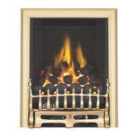
The pilot is visible through the left hand side of the front ceramic strip. Rotate the coals or peb-
bles for good viewing. Push in and turn the control knob to the SPARK position, and hold there
for a few seconds. If the fire has not been used for some time, hold the knob in this position for
longer, to allow any air in the pipes to be purged.
Continue turning anti-clockwise through the spark click to the PILOT light position, ensuring the
pilot has lit. If not, return the knob clockwise, and repeat.
When the pilot lights after the spark, keep the knob depressed for approximately ten seconds.
Now release the knob and the pilot should stay alight. If the pilot is extinguished during use, wait
three minutes before repeating the ignition procedure. To achieve the HIGH setting, push the con-
trol knob in slightly and continue turning anti-clockwise to the high position. The main burner
should light after a few seconds. To decrease the setting to LOW, turn the control knob clockwise
to the low setting.
To turn to the PILOT position from the HIGH or LOW positions, press the control knob in, and return to the pilot position and release.
To turn the fire OFF, keep the knob pressed in, return to the off position and release.
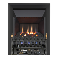
The pilot is visible through the left hand side of the front ceramic strip. Rotate the coals or pebbles for
good viewing.
Push the slide control knob fully downwards to the SPARK position, and hold there for a few seconds,
until the pilot light stays on. When the pilot light has established, release the slide control knob and it
will return to the LOW flame setting. If the pilot is extinguished during use, wait three minutes before
repeating the ignition procedure.
To achieve the HIGH setting, move the slide control knob upwards to the HIGH flame setting. The fire
can also be set to operate anywhere between HIGH and LOW by moving the control knob to an inter-
mediate position.
To turn the fire OFF, move the slide control knob upwards fully to the position marked ‘O’.
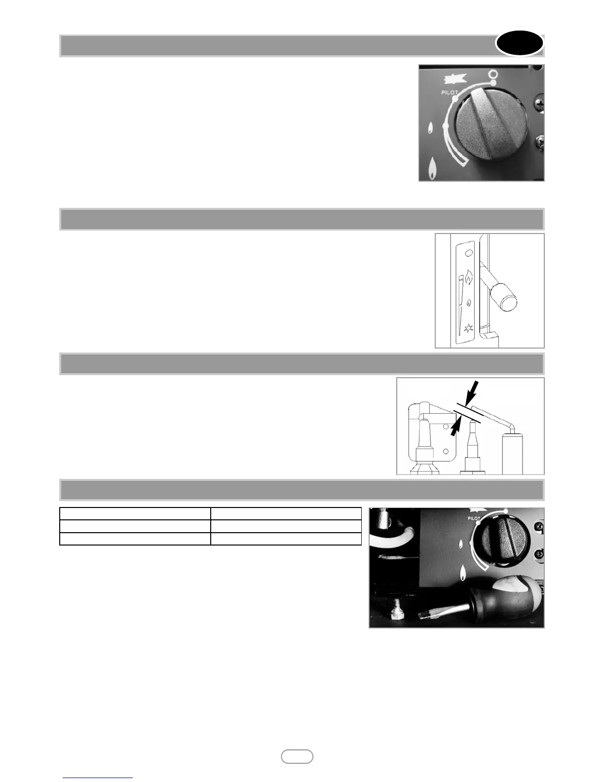
The spark gap (shown in figure 16) between the spark electrode and the thermocouple
should be 3.5 - 4.5mm to produce a good spark.
There should be no need to adjust this.
If under any circumstances the electric spark fails, the pilot may be lit manually by proceed-
ing with the ignition sequence as previously described, and after turning the control knob
through the spark position, the knob should be held in and the pilot lit with a taper.
Release the setting pressure test point screw, and attach a pressure gauge. Light the
fire on the HIGH setting. To commission the appliance, the burner pressure must be
in accordance with the figures stated in section 2.0 of these instructions.
The fire is factory set to achieve these pressures and any significant variation could
indicate a supply problem. If the pressure is too high, the gas supply meter may be
set incorrectly. This should be checked with the fire running and if necessary reset
by the gas supplier.
If the burner pressure is too low, then check the inlet pressure with the appliance running. If this is less than the inlet pressure stated
in section 2.0 of these instructions it will need to be reset by the gas supplier. If the setting pressure is too low, but the meter pressure
is acceptable, then a problem in the supply pipework is to be suspected.
Upon satisfactory checking of the burner pressure, turn the fire off, disconnect the pressure gauge and refit the test point screw. Light
the fire and check for gas soundness. In the event that the burner pressure is not in accordance with the figures stated in the data sec-
tion of these instructions, the appliance must not be commissioned, and the manufacturer should be contacted for guidance.
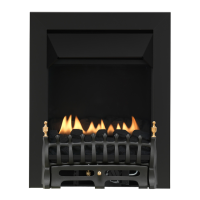
12.1 OPERATING THE FIRE - MANUAL CONTROL MODELS
GB IE
9
© 2010 Focal Point Fires plc.
Figure 14
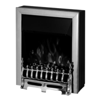
12.2 OPERATING THE FIRE - SLIDE CONTROL MODELS
Figure 15
12.3 SPARK GAP
Figure 16
Spark gap
12.4 SETTING PRESSURE
Control Type Test point location
Manual Shown in figure 17
Slide Between burner legs (RHS)
Fi
Figure 17