Parts Replacement HR 150, HR 410, LR150 and LR 410
IMPORTANT- all repairs must be carried out with the mains electrical supply
disconnected and by a competent person. Failure to do so may invalidate the warrantry.
1) Access To Electrical Connections.
Access to the electrical connections is via the back of the cabinet. All electrical connections are in the BIT 20
controller.
Remove the three screws securing the controller to the bracket. Rotate the controller to gain access to the
electrical connections.
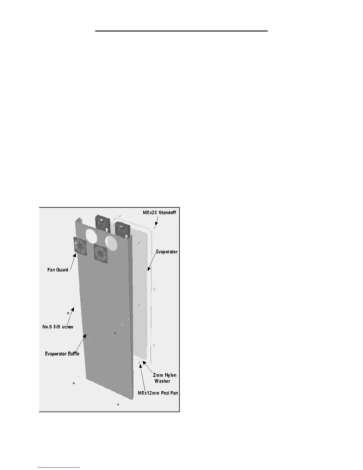
2) Evaporator Fan Replacement HR410
Remove the rear shelf supports from the cabinet interior.
Loosen the two retaining screws at the bottom of the airduct.
Remove the three screws securing the airduct to the top of the cabinet and ease it away from the rear of the
cabinet. (See Fig 1)
Sever the power cables and disconnect the earth wire from the motor.
Remove the plastic fan guard securing the fan motor to the duct.
Prior to fitting the replacement it is important to note the air is circulated across the evaporator plate and blows
through the fan into the storage area, an arrow can be found on the motor housing indicating airflow.
Secure the fan to the airduct using the fan guard incorporating the four fixing studs.
Note: It may be necessary to change the fan guard as unless care is taken it is possible to break the fixing studs
during this process.
Connect the power cables using suitable water tight cable connectors and connect the earth cable to the motor
housing.
Refit all panels ensuring they are located correctly and fitted securely.
Note:- The capillary
(Fig 1)