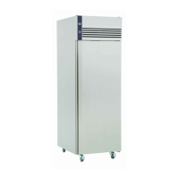
3) Air Probe Replacement HR410
Remove the Shelf supports and airduct as described in 2.
Remove the two screws securing the evaporator to the rear of the cabinet. (See Fig 1).
Unclip the air probe.
Disconnect the probe wires as described in 1.
Remove the two screws from the left-hand side of the condenser securing it to the cabinet.
Ease the condenser away from the back of the cabinet to expose the probe wires.
Release the probe and probe cable from the clips and remove it from the cabinet.
To replace the probe reverse the procedure ensuring probe and probe cable is secured firmly in the connector
block and retaining clips.
Refit all panels ensuring they are located correctly and fitted securely.
4) Compressor Fan Replacement.
Remove the screws securing the fan housing to the inside of the unit compartment and the rear right hand side of
the cabinet.
Remove the compressor electrical box and disconnect the fan cables from the terminals.
Slide the fan housing out of the unit compartment.
Remove the plastic fan guard securing the fan motor to the housing.
Note: It may be necessary to change the fan guard, as unless care is taken it is possible to break the fixing studs
during this process.
Prior to fitting the replacement it is important to note the air is circulated through the fan and blows across the
compressor, an arrow can be found on the motor housing indicating airflow.
Secure the fan to the housing using the fan guard incorporating the four fixing studs.
To refit reverse the procedure ensuring the electrical connections are firmly connected and all covers are located
correctly and fitted securely.
Note: On glass door models a ring mount fan motor is fitted, it is necessary to remove the rear fan guard to gain
access. Unscrew the four screws securing the fan to the housing and remove it. Prior to fitting the replacement cut
two portions from the ring of the fan to match the original and refit. On completion refit the rear fan guard.
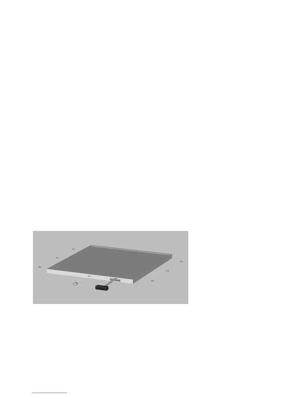
5 ) Controller Display Replacement.
Unplug the ribbon cable from the controller.
Remove top cover from the cabinet by unscrewing the four screws securing it to the sides and the three screws
from the front underside. See Fig 2.
Slide the cover forward and lift it from the cabinet.
Pull the ribbon cable out from behind the condenser.
Depress the two retaining lugs on either side of the display and remove it.
To fit the replacement reverse the procedure ensuring all covers are located correctly and fitted firmly.
(Fig 2)
6) Controller Replacement.
Remove the controller as described in 1.
Unplug the ribbon cable and disconnect all electrical connections.
To replace reverse the procedure ensuring all electrical connections are attached firmly in the correct positions.
Refit the controller to its bracket.
To access the controller and for resetting the parameters see the instructions on page 5.