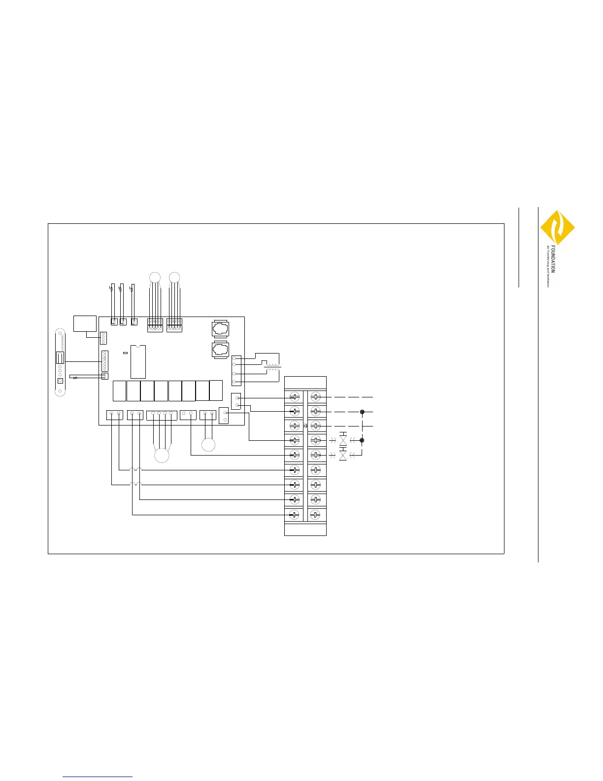
Wiring Diagrams
Water Cassette Wiring Diagram
PCE-06-08-PS
JP0
White
LOW
Red
Red
White
MED
HIGH
Brown
M
N
AUX1 AUX2
JP6
JP14
JP5
JPH
Wall Pad
JP10
JIPH
JP13
JIPC
JP11
JP7
JP9 JP8
SM3,4
SM1,2
Legend:
JP0----Short is master
Open is slave
JP1----Transformer
JP2----Power supply
JP3----2-way valve of Cooling
JP4----Drainage pump
JP5----Fan motor
JP6----Remote receiver
JP7----Stepping motor
JP8----Stepping motor
JP9----Stepping motor
JP10---Stepping motor
JP11---Room TEMP. sensor
JP13---Wall pad
JP14---Float switch
JPH----2-way valve of Heating
JIPH---Coil TEMP. sensor of Heating
JIPC---Coil TEMP. sensor of Cooling
AUX1---Auxiliary 1 for heat
AUX2---Auxiliary 2 for cool
T
A1
A2 A2
A1
Black
M
Yellow/Green
JP2
JP4
JP3
JP1
Black
Blue
N CV HV
L
TB
CPU
FP-68-80 KM4
 Loading...