S Series User Manual www.fox-ess.com P a g e | 12
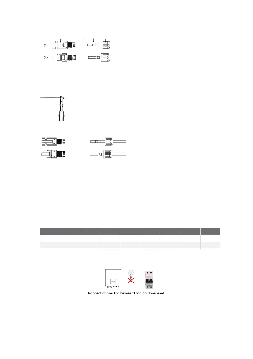
Plug Pin contact Cable nut
➢ Insert striped cable into pin contact and ensure all conductor strands are captured in the pin contact.
➢ Crimp pin contact by using a crimping plier. Put the pin contact with striped cable into the corresponding
crimping pliers and crimp the contact.
➢ Insert pin contact through the cable nut to assemble into back of the male or female plug. When you feel or
hear a “click” the pin contact assembly is seated correctly.
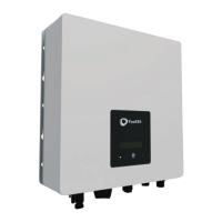
➢ Unlock the DC connector
- Use the specified wrench tool.
- When separating the DC+ connector, push the tool down from the top.
- When separating the DC - connector, push the tool down from the bottom.
- Separate the connectors by hand.
➢ Grid Connection
S series inverters are designed for single-phase grid. Voltage range is
220/230/240V; frequency is 50/60Hz. Other
technical requests should comply
with the requirement of the local public grid.
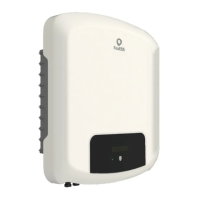
Note: A micro-breaker should be installed between inverter and grid; any load SHOULD NOT be connected with the
inverter directly.
Step 3: AC Wiring
➢
Check the grid voltage and compare with the permitted voltage range (refer to technical data).
➢
Disconnect the circuit-breaker from all the phases and secure against re-connection.