13
Step 2: DC Wiring
• Turn off the DC switch.
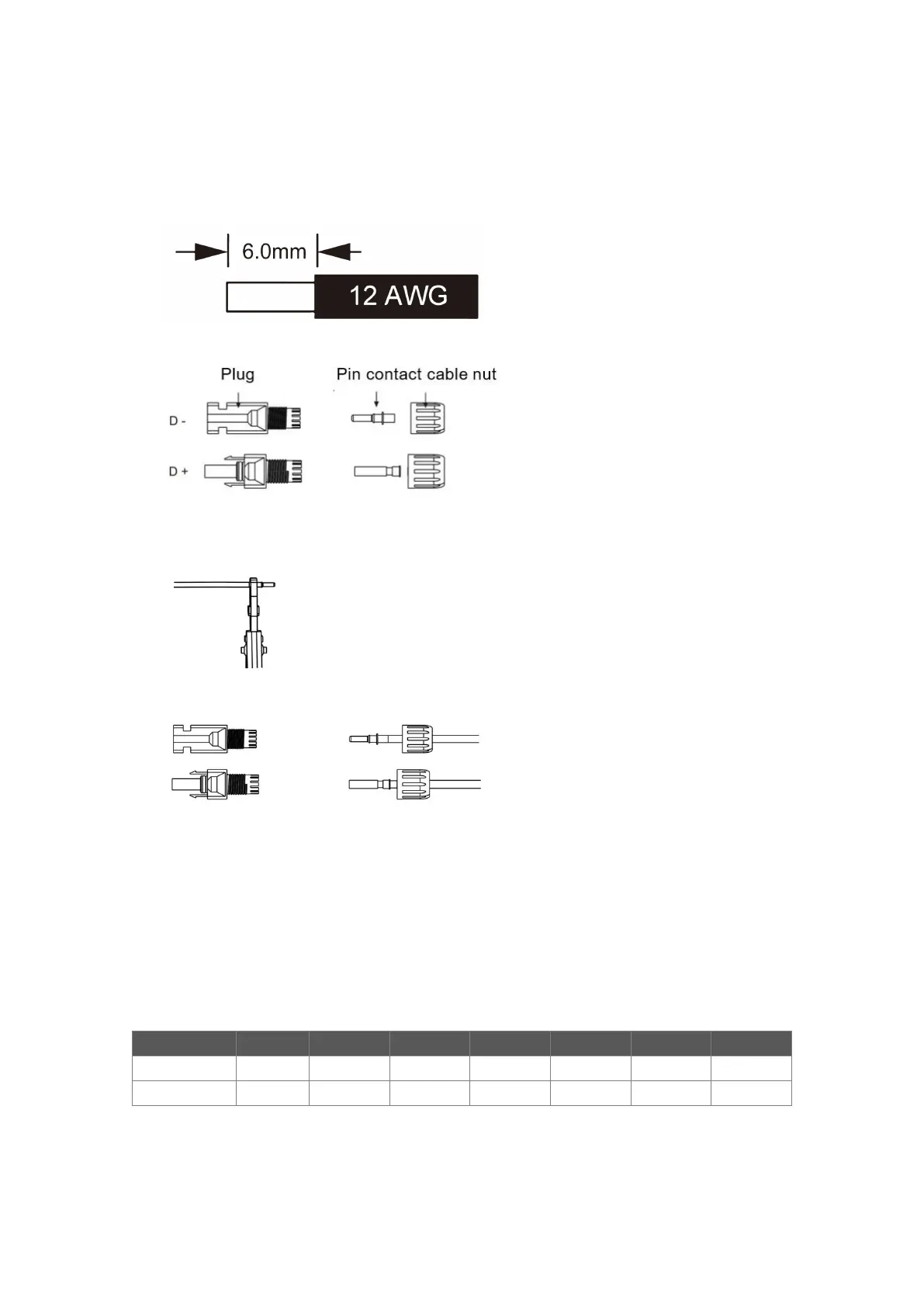
• Choose 12 AWG wire to connect the PV module.
• Trim 6mm of insulation from the wire end.
• Separate the DC connector as below.
• Insert striped cable into pin contact and ensure all conductor strands are captured in the pin contact.
• Crimp pin contact by using a crimping plier. Put the pin contact with striped cable into the
corresponding crimping pliers and crimp the contact.
• Insert pin contact through the cable nut to assemble into back of the male or female plug. When you
feel or hear a “click” the pin contact assembly is seated correctly.
• Unlock the DC connector
- Use the specified wrench tool.
- When separating the DC + connector, push the tool down from the top.
- When separating the DC - connector, push the tool down from the bottom.
- Separate the connectors by hand.
• Grid Connection
S Series (G2) inverters are designed for single-phase grid. Voltage range is 220/230/240V;
frequency is 50/60Hz. Other technical requests should comply with the requirement of the local
public grid.
Note: A micro-breaker for max output overcurrent protection device shall be installed between inverter
and grid, and the current of the protection device is referred to the table above, any load SHOULD NOT



 To Next Page