4. SILENCER HOUSING MOUNTING INSTRUCTIONS
The ‘SCL K-MS’ series was designed to provide maximum
flexibility in the positioning of the silencer housings to meet
various installation configurations.
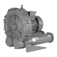
The blower is supplied with the silencers configured as in Fig. 1
If this configuration needs to be modified, proceed as
follows:
1. Identify the desired configuration (Fig. 2, Fig. 3, Fig. 4).
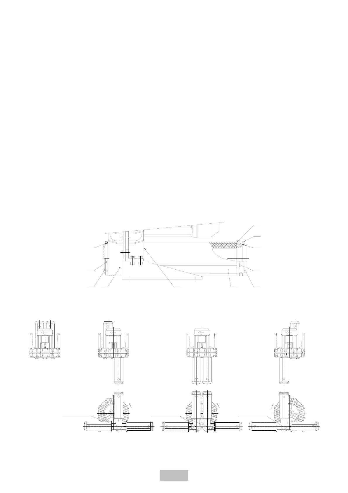
2. Disassembly of the silencer housing:
2.1 Remove #908 screws, taking away #723 flange with the
#426 O-ring.
2.2 Remove the #906 screws.
2.3 Take away the #700 silencer from the unit along with the
#424 gasket.
3. Disassembly of the #730 blind flange:
3.1 Remove the #909 screws, taking away the #730 flange
along with the #427 gasket.
Reassemble in reverse order-do not forget the #424 #426 and
#427 gaskets.
If needed, reconstruct #425 seal using Loctite 598 or similar,
after cleaning the sealing surfaces of any existing sealant.
4.1 USING THE 90° MANIFOLD KIT TYPE CK (accessory)
The 90° manifold can only be installed on the #162 cover ports
and as shown in the Figures below, there are multiple
configurations.
The 90° manifold kit type CK comes supplied with;
1 x manifold
1 x gasket and
4 x M8x25 UNI 5739 screws.
To mount the 90° manifold, proceed as follows:
1. Disassemble the silencer housing (see point 2)
2. Place the gasket between the #162 cover and the 90°
manifold and seal with the M8x25 UNI 5739 screws.
Assemble the silencer housing in reverse order-do not forget the
#424 and #426 gaskets.
GB - 17/39
Fig.1 Fig.4
90° manifold
Fig.4 with 90° manifold
Fig.3
Fig.3 with two 90° manifolds
90° manifolds
Fig.2
Fig. 2 with 90° manifold
90° manifold
723
426
425
906
908 700162 909
730
424
427