Installation and connection
11
2 Installation and connection
The reactive power control relay RM 2112
and RM 2106 respectively can be connected
in a number of different ways. The main
connection methods are described below.
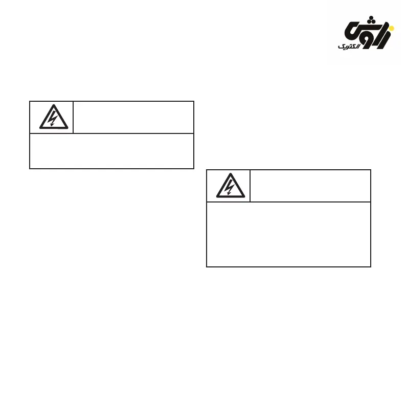
Important information:
The control relay should be disconnected
from the mains during installation.
2.1 Installation
The reactive power control relay is installed
from the front in a control panel space
measuring 138 x 138 mm and is xed in place
using the mounting screws of the front panel.
As accessories (protection kit; see section
8) insulated xing screws are available.
These can be used to install the control
relay into switchgear cabinets and cubicles
of protective class II. Also a sealing ring is
part of the protection kit, which must be used
when installing the control relay in switchgear
cabinets and cubicles of protection class IP 54.
The pre-assembled xing clamps ensure
speedy and secure assembly. The electrical
connection is created by means of plug-in
connectors which are also included in the
delivery.
2.2 Voltage connection
Reactive power control relay obtains its
voltage supply via terminals ”L” and ”N” (see
gure 2, item ’l’).
A phase conductor is to be connected to
terminal ”L” and neutral conductor to terminal
”N”. For advanced connection variations see
sections 2.7 to 2.10.
Important information:
The reactive power control relay is designed
for voltage supplies of up to 240 V AC.
The connections for the supply voltage are
to be fused externally with 4 A max.
In the case of mains networks that do not
facilitate voltage tapping in the 220 V AC
to 240 V AC range (either phase/phase or
phase/neutral), a voltage transformer must
be used for the power supply for the control
relay. (See section 2.9 )
za
voshelectric.ir