RM 2106 / 2112
12
2.3 Current transformer connection
Outputs S1 and S2 of the current transformer are
connected to terminals S1 and S2 (Figure 2, item
’j’) of the control relay. To keep the load of the
current transformer as low as possible, the feed
lines should have a adequate cross section.
It is permissible for connector S1 or S2 of the
current transformer to be grounded.
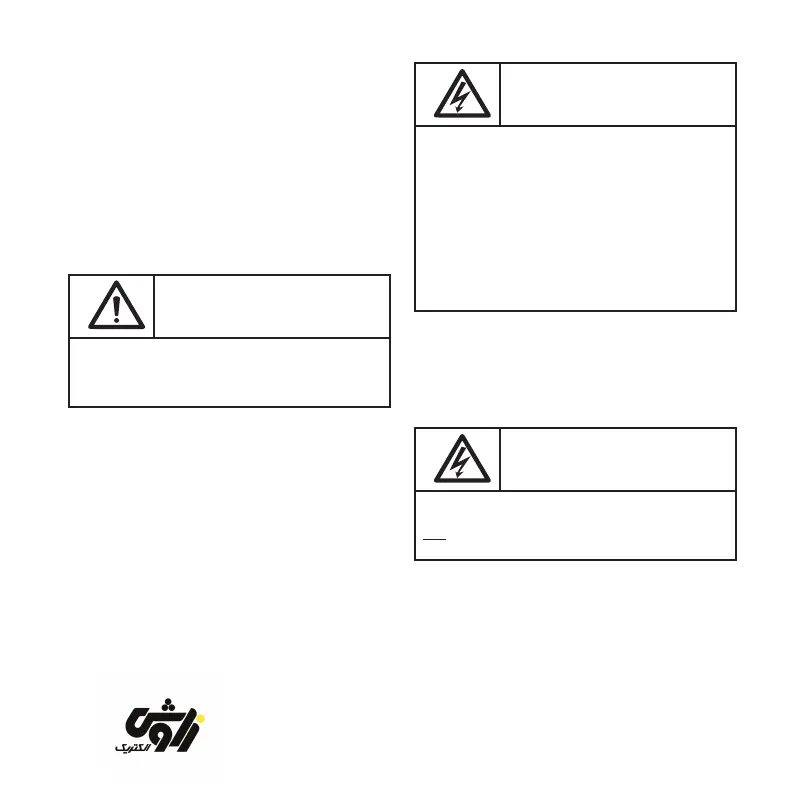
Caution:
The nominal current in the current transformer
path may not exceed 5 A.
Note:
After connection it is necessary to remove
the short-circuit jumper on the current
transformer, if present.
2.4 ”Meas” measuring voltage connection
This connection can be used to switch the
control relay to a different measuring procedure
for monitoring overcurrent (see section 2.8 ).
This terminal ”Meas” (Figure 2, item ’k’) is not
used in the standard connection.
Important information:
The nominal voltage between the ”Meas” and
”N” connectors may not exceed 240 V AC.
The voltage between the ”Meas” and ”L”
connectors may not exceed 420 V AC.
If ”Meas” is connected directly to a phase
conductor, then this is to be secured exter-
nally with a maximum of 4 A.
2.5 Switching contacts
The shared pole of all switching contacts
(Figure 2, item ’m’) is connected to terminal
”L” of the voltage supply.
Important information:
The outputs of the switching contacts do
not have oating potential.
When the switching contacts are switched, the
same voltage is applied as is used to supply
voltage to the control relay (connection ”L”).
zavoshelectric.ir