RM 2106 / 2112
28
When automatic response current identication
is switched on (-4-), the response current
is adapted to the connected power factor
correction system to optimum effect. The
response current determined can be read
under setup code -5- but cannot be altered.
When automatic response current identication
is switched off (-4-), the response current can
be set between 0.02 and 2 A in steps of 0.01 A.
The correct setting for 400 V AC mains
voltage and current transformer with 5 A AC
secondary voltage can be found in Table 2.
For other mains currents or current transformers
with unlisted primary or secondary current, the
response current can be calculated according
to the following formula:
I
A
= Response current to be set in A
Q = Capacitor stage rating of the lowest
stage in var (not the overall power of
the system)
U = Mains voltage in V (phase to phase)
k
i
= Current transformer ratio (primary/
secondary current)
k
u
= Voltage transformer ratio (primary/
secondary voltage) (if any)
I
QVk
Uk
V
Qk
Uk
A
u
i
u
i
==
⋅⋅
⋅⋅ ⋅⋅
⋅⋅ ⋅⋅
≈≈⋅⋅
⋅⋅
⋅⋅
065
400
3
150
2
2
.
4.4 Automatic response current
identication -4-
If set to On the control relay operates with the
response current determined at initial start-
up and the values determined for the switch
outputs. These values can be read under
points -5- and -6- .
If set to Off the response current (setup code
-5-) and the value of the switch outputs (-6-)
must be programmed manually.
This setting is to be selected if the low voltage
network is fed by several transformers
switched in parallel.
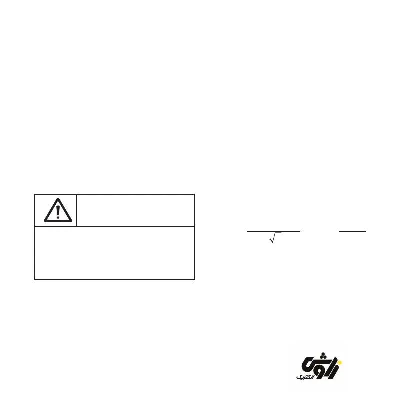
Important:
If ”OFF” is set, connection must be as shown
in connection diagrams 3, 4, 5 or 6. Deviations
are not signalled and are not corrected
automatically.
4.5 Response current -5-
The response current describes the width
of the control band (see gures 7 to 9). The
greater the value, the broader the control band.
zavoshelectric.ir