RM 2106 / 2112
14
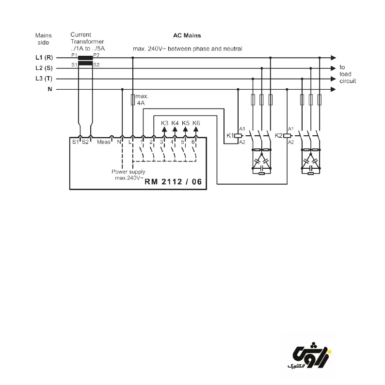
Figure 3 Single phase connection
2.7 Single phase connection
The connection diagram above shows the
same connection as the one printed on the
back of the control relay.
The voltage signal for power factor measurement
is received in parallel with the voltage supply.
The terminal ”Meas” is not in use.
In this connection variant, only the 5th, 7th,
11th and 13th harmonics of the voltage are
used to calculate the harmonic overcurrent in
the capacitor.
This connection variant can be chosen if the
above-mentioned harmonics are sufcient
for monitoring overcurrent or if overcurrent
monitoring has been completely switched off
(setup code -2-).(see section 4.2)
Current transformer and terminal ”L” should
be attached to the same phase conductor:
Either L1, L2 or L3.
zavoshelectric.ir