Control relay setup
25
Note:
During ”setup mode”, no controlling
activities are carried out by the control
relay.
If no key is pressed for about 15 minutes,
setup mode is quit automatically.
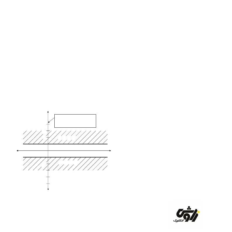
4.1 Target power factor setting -1-
The required target power factor can be set
between 1.00 and ind. 0.85 in steps of 0.01.
This for example results in the following
control characteristic for a target power factor
of 1.00:
2
3
-2
-3
ind
cap
The scale spacing
corresponds to 0.65*
smallest stage power
Regenerative power
Reactive power
Activation
Deactivation
Active power
Figure 7 Target power factor 1.00
In this setting the control relay attempts
to minimize reactive power irrespective of
active power.
The control relay creates a tolerance band (or
control band) around its target (in this case
the target is to permit no reactive power). If
the operating point is within the control band,
then the control relay will not carry out any
further switching.
For a target power factor of 1.00 this means
that the permitted reactive power may not
exceed 0.65 times the lowest capacitor
stage.
If, on the other hand, the work point is outside
of the control band, the control relay will
attempt to reach the control band with the
smallest possible number of switchings by
means of specic activation and deactivation
procedures.
zavoshelectric.ir