RM 2106 / 2112
26
3
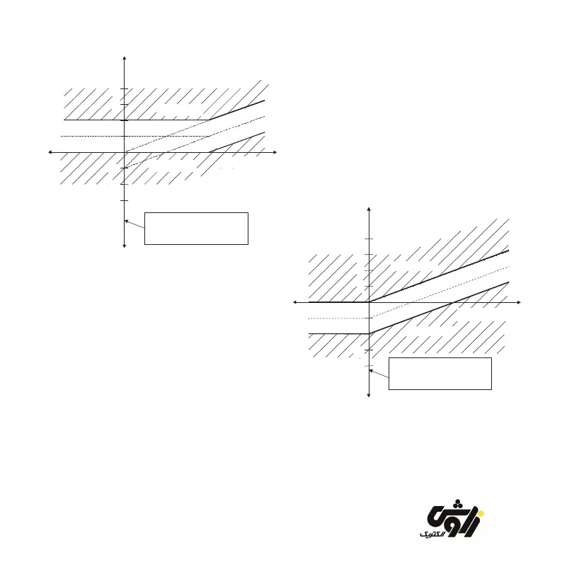
Reactive power
4
-1
ind
cap
The scale division
corresponds to 0.65*
smallest stage power
-2
-3
Regenerative power
Acive power
Deactivation
Activation
Figure 8 Target power factor 0.92
In addition to the target power factor setting
1.00, the control relay can also be set to a
target power factor between 0.85 and 0.99.
A distinction is made here between two
different control bands. The control bands
are distinguished by a large or small zero
preceding the decimal point in the target
power factor input.
The type of control band shown in gure 8
can be achieved by means of a large zero
preceding the decimal point of the target
power factor setting.
The target power factor forms the upper limit
of the control band. The control relay always
attempts to obtain a better power factor.
However, the control band levels off at low
values of active power in order to avoid
overcompensation.
For regenerative power (active power supplied
to the mains) the control band stays leveled
off for regenerative power.
Reactive power
2
3
ind
cap
Regenerative power
The scale division
corresponds to 0.65*
smallest stage power
Activation
Reactivation
Active current
1
-3
Figure 9 Target power factor o.92
If generators are active in mains parallel
mode, even small amounts of inductive
reactive powers are unwanted in the mode of
regenerative power.
zavoshelectric.ir