Framo Cargo Pump SD125-5/ SD150-5
INSTRUCTION FOR MAINTENANCE AND REPAIR
No.
Date/sign.:
Page:
Rev. B:
1000-0131-4
Jan99/AGAa
11 of 21
22Feb06/JEB
Wear Rings
When mounting new wear rings be sure that support ring is tighten until metallic contact.
Impeller
To ensure optimal friction between impeller hub and impeller the contacting surfaces have to be
clean and dry (free from grease) before assembling.
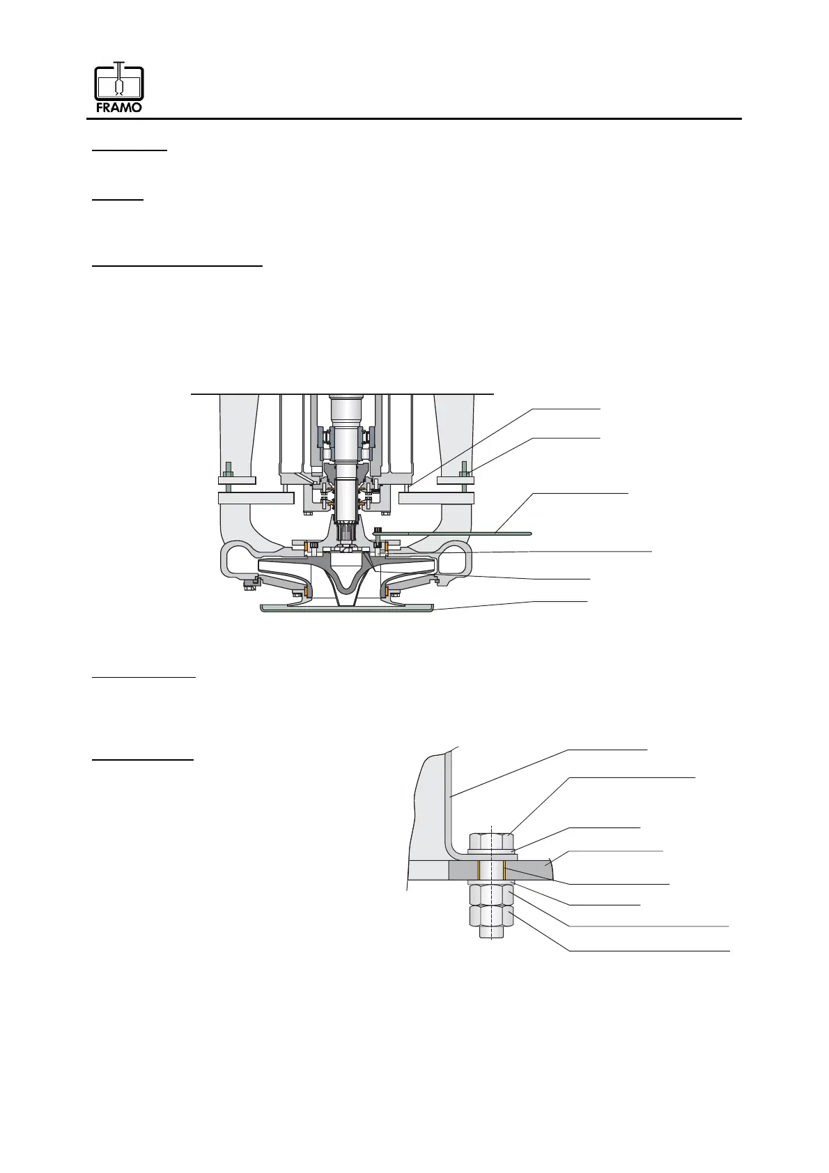
Volute casing with impeller
Slide volute casing and impeller into suction well. Framo seal element is to be placed on top of
impeller when volute casing is in position below impeller hub. Check position of the guiding pin in
flange connection between pump unit and volute casing (see fig. 3).
Lift the complete unit with 2 lifting bolts M12x250 until these bolts can be replaced with the original
bolts. Assemble the bolts for impeller hub and volute casing. Tighten all bolts evenly by using the
torque wrench. To avoid rotation of impeller hub use the anti rotating tool.
Ù«·¼·²¹°·²
Ô·º¬·²¹¾±´¬-
Þ±´¬º±®·³°»´´»®¸«¾
Í»¿´®·²¹-
ß²¬·®±¬¿¬·²¹¬±±´
Í´·¼»¬±±´
Fig. 11
Reducing plates
Replace the reducing plates before fastening upper wear ring support (see fig. 3 and 4).
Bottom support (arrangement with counter nut)
Tighten nuts as follows (fig. 12):
1) Assemble upper nut, use 190 Nm torque.
2) Tighten all bolts one more time,
use 190 Nm torque.
3) Assemble lower nut, use 190 Nm torque.
Í«°°±®¬®·²¹
Ú¿-¬»²»®-
Ó¿¬»®·¿´
Ï«¿´·¬§
æͬ¿·²´»--
æßìóèð
Í«°°±®¬¾®¿½µ»¬
Ë°°»®²«¬ø̱®¯«»ïçðÒ³÷
Ú´¿¬©¿-¸»®
ݱ¿¬·²¹¬±«½¸«°
Ú´¿¬©¿-¸»®
Ô±©»®²«¬ø̱®¯«»ïçðÒ³÷
Fig. 12