Framo Cargo Pump SD125-5/ SD150-5
INSTRUCTION FOR MAINTENANCE AND REPAIR
No.
Date/sign.:
Page:
Rev. B:
1000-0131-4
Jan99/AGAa
10 of 21
22Feb06/JEB
2.3 Assembling after maintenance
CHECK ALL SEAL ELEMENTS, BACK-UP RINGS, SEAL ELEMENT GROOVES AND
SEAL FACES. PAY SPECIAL ATTENTION TO THE TEFLON RINGS AND BE
ABSOLUTE SURE OF NO DEFORMATION NOR RADIAL GROOVES.
NEVER INSTALL DAMAGED SEAL RINGS. CHECK SEAL FACES ON PUMP AND BE
SURE OF NO CORROSION, CRACKS, DIRT ETC.
- USE ONLY GENUINE SPARE PARTS -
ALL SCREWS AND NUTS HAVE TO BE ASSEMBLED WITH SPECIFIED TORQUE.
IF NO TORQUE IS SPECIFIED, USE THE FOLLOWING TORQUE:
ACID RESISTANT BOLTS AND NUTS, QUALITY A4-80
M6 M8 M10 M12 M16 M20
9 Nm 22 Nm 45 Nm 80 Nm 190 Nm 370 Nm
All bolts and nuts are to be fastened using a torque wrench.
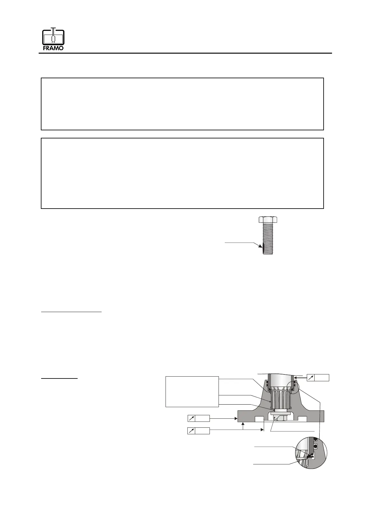
Acid resistant bolts must be partly coated with a thin
layer of "molybdenum disulphide" (Molykote) prior to
assembling. Apply a small amount to the lower part of
the threads, see fig. 9.
All assembling has to be done in reversed way according to the dismantling sequence.
PAY SPECIAL ATTENTION TO THE FOLLOWING POINTS:
Lip seal arrangement
Use assembling cylinder to fix the ceramic sleeve into correct position. Do not remove the cylinder
before all Framo shaft seals has been installed. When assembling lip seals be sure that support
ring is tightened up until metallic contact. This to avoid screws to loosen. The double lip seal shall
be mounted as shown in fig. 7, chapter 2.2.
Note! The ceramic sleeve must be handled very carefully as it is very brittle and may
crack if dropped.
Impeller Hub
Prior to mounting of impeller hub, apply
a thin layer of Molykote TP-42 to the
shaft spline and shaft steering as shown
in fig. 10.
Check that the drive ring is in correct
position at the end of the ceramic
sleeve.
When assembling impeller hub, be
careful not to damage seal rings.
Be sure to lock the impeller hub bolt
properly. Locking washer must be
replaced. Check the shaft alignment
according to fig. 10.
0.05
Drive Ring
Securing ring
Locking washer
Hub
Lower part of
shaft spline
Hub
0.04
0.04
Prior to mounting
apply a thin layer
of Molykote TP-42
at these locations
Fig. 10
ß°°´·½¿¬·±²
¿®»¿
Fig. 9