QUICKSTART GUIDE
Electrical Installation
3
Electrical Installation
Wiring Guidelines
1. Mount the drive as close as possible to the service entrance panel. Wire directly to the service entrance.
Do not connect to a sub-panel.
2. Use a dedicated branch circuit for the drive.
3. Route motor wiring out of the building as soon as possible. Separate input power and motor wiring by
at least 8 in. (20.3 cm).
4. Cross over other branch circuits and facility wiring at a 90 angle. If it is necessary to run wiring in par-
allel, separate by at least 8 in. (20.3 cm).
5. All control wiring—sensors, switches, transducers, etc.—should be in a separate conduit routed individ-
ually, not parallel, from high voltage wiring. In addition, any shielded cables should be properly
grounded.
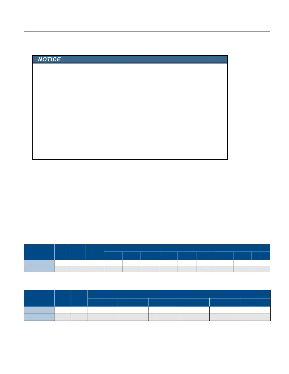
Fuse/Circuit Breaker and Wire Sizing
Verify that the dedicated branch circuit for the drive is equipped with a properly-sized circuit breaker.
1
Based on a 3% voltage drop.
Maximum Motor Cable Length
1
Based on a 5% voltage drop.
NOTE: Flat-jacketed submersible motor cable is recommended. Cable lengths shown are for the highest
power motor supported.
Risk of damage to VFD
, or malfunction can occur.
Follow all wire routing and grounding instructions carefully. Inductive currents caused by parallel wiring,
or close proximity between high voltage and control wiring can cause unexpected behaviors.
• Do not run input power and motor wires in the same conduit.
• Do not run motor wires from multiple VFDs in common conduit.
• Do not run control wiring parallel with high voltage wiring.
• Do not install a magnetic contactor or disconnect in the motor circuit.
• Do not run VFD wiring parallel with house or out-building wiring.
• Do not use aluminum wires for VFD connections.
• Do not use with a Ground Fault Circuit Interrupter (GFCI).
• All wiring must comply with the National Electrical Code and local codes.
• Improper splicing or damage to motor cable insulation may expose the conductor(s) to moisture and
can produce motor cable failure.
• For retrofit application, make sure to check the integrity of power and motor leads. This requires
measuring the insulation resistance with a suitable megohm-meter.
Model
Input
Volts
Rated
Input
Amps
Fuse or
Breaker
Amps
AWG Copper Wire Sizes, 90° C Insulation, and Panel to Drive Cable Lengths (in feet)
1
10 8 6 4 3 2 1 1/0 2/0
SDCP-SUB2043
460 V 42 A 50 A 281 417 639 969 1172 1433 1711 2041 2443
SDCP-SUB1023
230 V 46 A 50 A 124 185 284 432 523 640 766 916 1098
Model
Output
Volts
Rated
Output
Amps
AWG 600V Copper Wire Sizes, 90° C Insulation, and Motor Cable Lengths (in feet)
1
10 8 6 4 3 2
SDCP-SUB2043
460 V 30 A 410 650 1030 – – –
SDCP-SUB1023
230 V 32.5 A 190 310 490 760 950 1000
 Loading...