QUICKSTART GUIDE
Electrical Installation
6
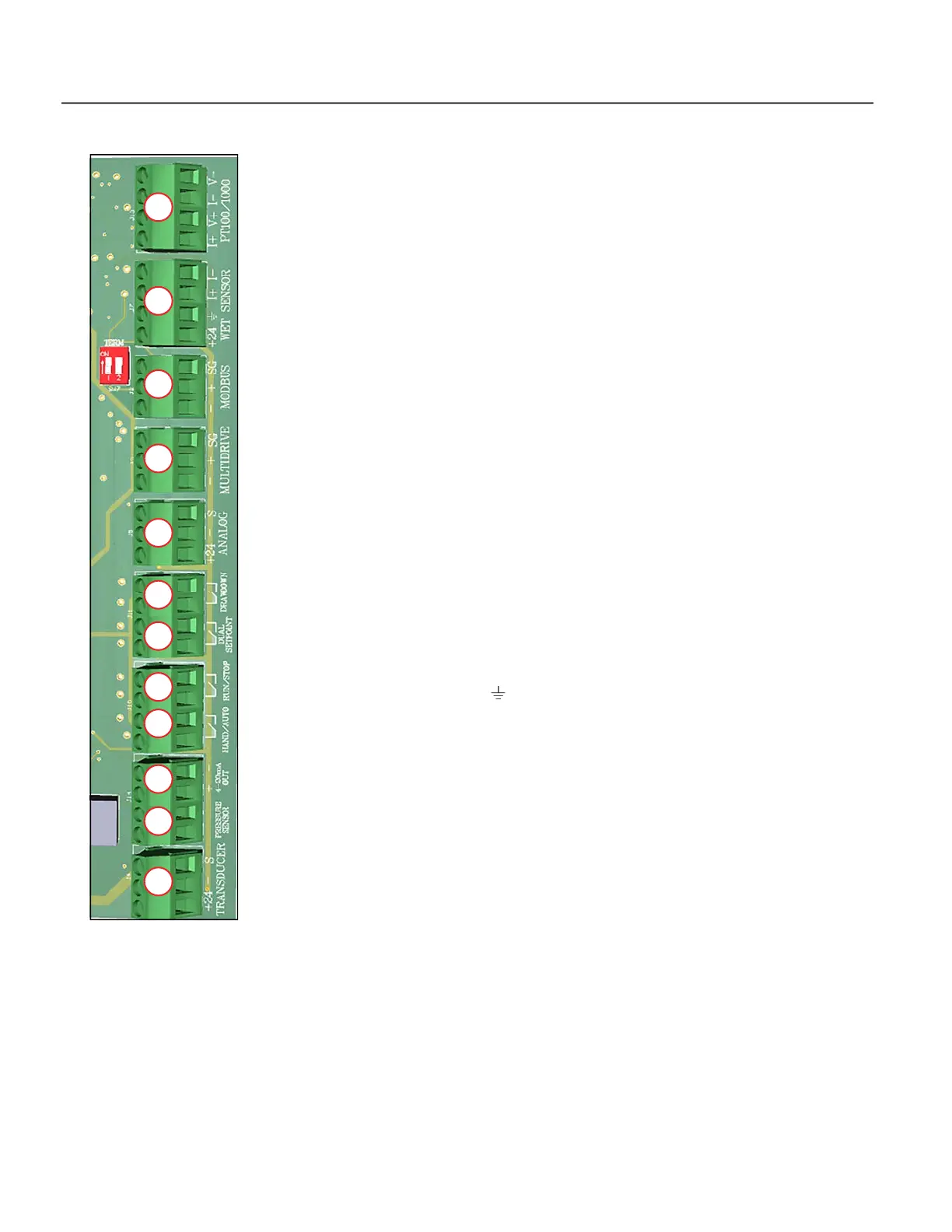
Control Circuit Connections
NOTE: All control terminals accept wire sizes from 12 to 26 AWG and should be tightened to a torque of 3
in-lbs (0.35 Nm) maximum.
1. Pressure Transducer – When using a pressure transducer:
• Connect the red cable lead to the TRANSDUCER +24 terminal.
• Connect the black cable lead to the – terminal.
• Connect the shield wire (when applicable) to the S terminal.
NOTE: A 200 psi transducer is required by default.
2. Pressure Sensor – When using a standard pressure sensor:
• Connect the sensor leads (interchangeable) to the Pressure Sensor terminals.
3. Hand/Auto Switch – Connect a dry contact switch to this terminal to select Hand or Auto modes.
The drive will regulate pressure in auto mode when this terminal is open. The drive will run at a fixed
frequency with this terminal is closed. The frequency can be selected via the up/down buttons.
4. Run/Stop Switch – The drive will operate regularly when this terminal is open. The drive will stop
the motor if this terminal is closed.
NOTE: When Stop is selected, the drive motor will stop even if the drive is in Auto mode.
5. PT100/1000 – Connector for external RTD temperature sensor.
• I+ Positive connection for excitation current circuit for two, three, and four wire PT100/PT1000 RTD
sensors.
• V+ Positive connection for voltage sensing circuit for two, three, and four wire PT100/PT1000 RTD
sensors.
• I-/V- Negative connections for the excitation and voltage sensing circuits for two, three, and four
wire PT100/PT1000 RTD sensors
6. Moisture Sensor – The WET SENSOR terminal supports the Franklin Electric Moisture Sensor.
• Connect the red cable lead to the +24 terminal.
• Connect the black cable lead to the terminal.
• Connect the white cable lead to the I+ terminal.
• Connect the green cable lead to the I– terminal.
7. Dual Setpoint – The drive will regulate to Pressure Setpoint 1 when this terminal is open. Pressure
Setpoint 2 is active when this terminal is closed.
8. 4-20mA Out – The 4-20mA Out allows the user to repeat the incoming Pressure Transducer 4-
20mA signal. Additionally, DIP SW1 Position 4 can be toggled to output a 4-20mA signal of the
motor speed.
9. MultiDrive – Connections should be from each terminal to the corresponding terminal on the next
drive(s) in series.
• Shield wires should be connected together and grounded on one end only.
• Termination Switch 2 (to the left of the connector) should be in the Up (On) position for the first and
last drives in the series.
10. Modbus – Terminals –, +, and SG provide RS-485 connections for Modbus communications to an
external computer-based monitoring or control device.
• Termination Switch 1 (to the left of the connector) should be in the Up (On) position for communica-
tions.
11. Analog Input – Not Currently Used.
12. Drawdown – Not Currently Used.

 Loading...