4. Remove the CGI piping between the engine and
aftertreatment device (ATD).
5. On the workbench, remove the CGI bellows from
the exhaust piping. Do not damage the piping.
NOTE: The following step, and its substeps, is
to be done without the bellows installed. This
will align the pipes so that the bellows can be
installed correctly.
6. Install the CGI piping (without CGI bellows) and
align piping.
6.1 Attach the aft CGI pipe to the ATD.
6.2 Attach the forward CGI pipe to the en-
gine.
NOTICE
When the CGI pipes and bellows are installed,
there should be approximately 3/4 inch (19 mm)
clearance from the main bellows. Contact between
the bellows could result in an exhaust leak, which
in this case may allow ingestion of contaminants
into the engine causing engine damage.
6.3 Use a straightedge to align the pipes so
that the pipe ends that attach to the bel-
lows are parallel and concentric.
NOTICE
When shortening the CGI pipe(s), it is critical to
leave a minimum of 1 inch (25.4 mm) of straight
pipe on the end of each CGI pipe to allow for pipe
insertion and clamp clearance. Failure to do this
could result in an exhaust leak, which in this case
may allow ingestion of contaminants into the en-
gine causing engine damage.
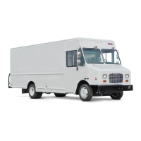
7. Once the pipes are aligned, measure the pipe
gap between the CGI pipes and record the dis-
tance. See
Fig. 9, Ref. A.
The existing pipe gap is designed at 10 inches
(254 mm). A 10.75 inches (273 mm) pipe gap is
required for the replacement CGI bellows and
clamps. This requires one or both of the CGI
pipes to be shortened.
8. Using a yellow paint pen, mark the pipes 1.5
inches (38 mm) in from the end of each pipe.
These two marks will be used to center the bel-
lows between the two pipes.
9. Once the pipes are correctly aligned and sepa-
rated at the correct distance, secure the aft CGI
pipe to the ATD and to any CGI pipe support
brackets.
10. Remove the forward CGI pipe from the truck.
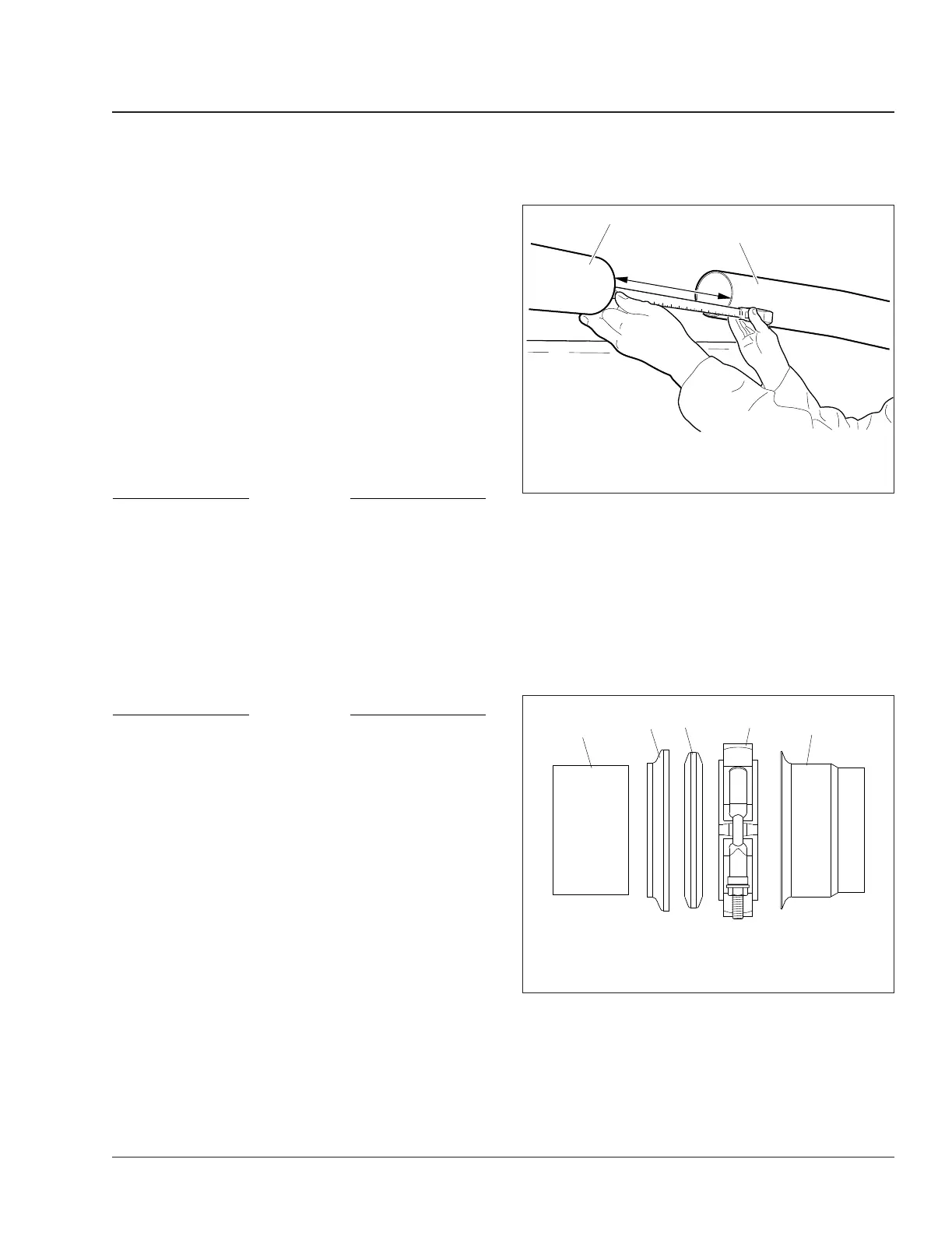
11. Slide the slip clamp, with the retaining ring and
graphite gasket ring, on the aft CGI pipe. See
Fig. 10 for proper installation.
12. Slide the new bellows onto the aft CGI pipe as
far as it will go. See
Fig. 11, Ref. A. Measure-
ment A should be at least 7/16 inch (10 mm)
past the face of the flange.
02/23/2011 f490457
1
2
A
A. Measure the pipe gap.
1. CGI Aft Pipe 2. CGI Forward Pipe
Fig. 9, Measuring the Pipe Gap (typical)
01/29/2010
1
2
3
4
5
f490415
1. Aft CGI Pipe
2. Retaining Ring
3. Graphite Gasket
4. Slip Clamp
5. CGI Bellows
Fig. 10, Aft Facing Slip Clamp Installation
Exhaust 49
Century Class Trucks Maintenance Manual, January 2016 49/5
 Loading...